Page last updated in January 2021
GRINDING MACHINES (continued)
Churchill Roll Grinders.
When Churchill became part of the group, production of their world-famous steel mill roll grinders and various other machines transferred to Peterborough. A new 2-bay extension (bays 4 and 5) to the No. 2 factory of Newall Engineering was dedicated to the assembly of these very large and heavy machines. Massive concrete foundations were cast beneath the floor of one of the new bays to provide the rigidity and isolation that would be required for these monsters, some of which could weigh over 100 tonnes.
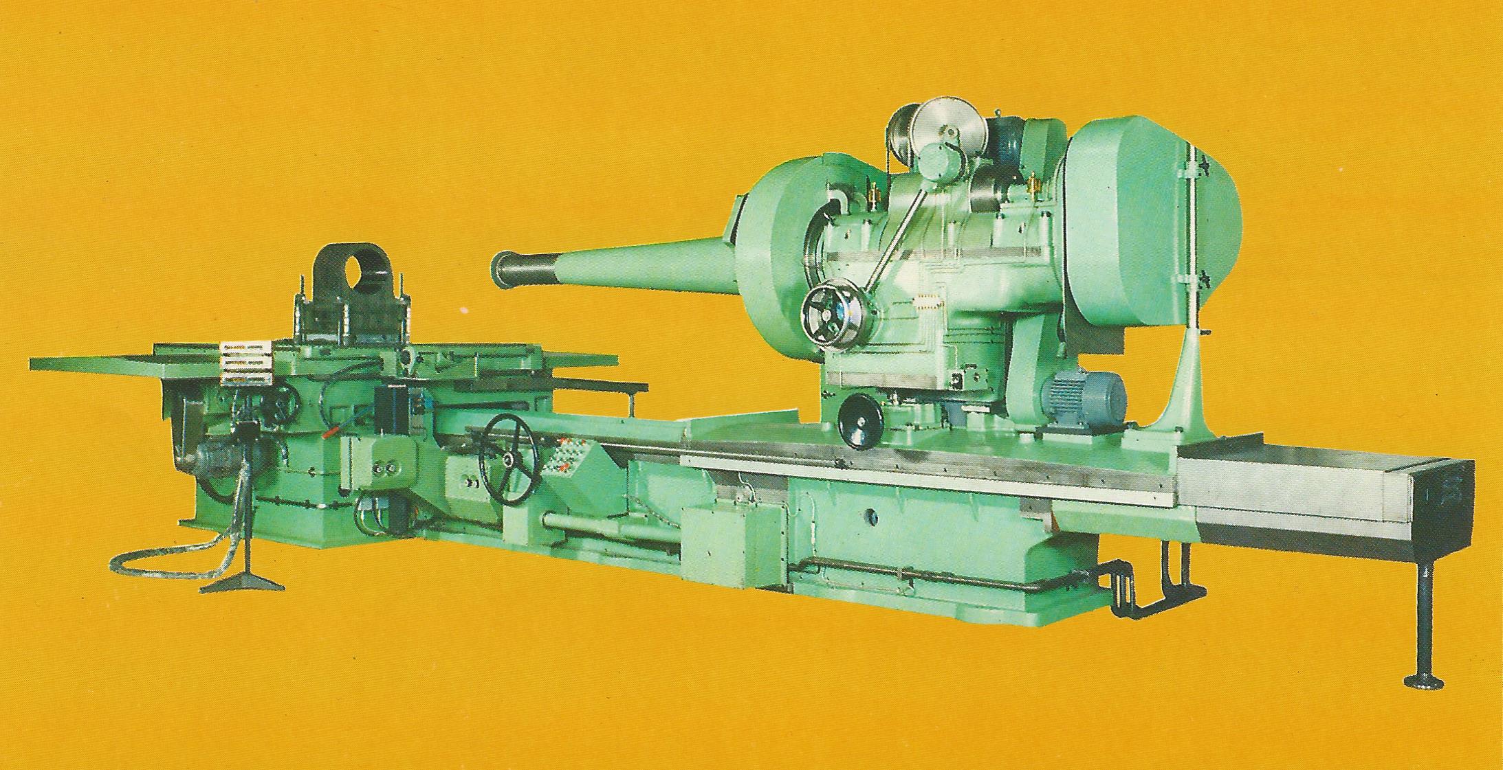
Traversing Wheelhead Roll Grinder
Churchill had designs for both traversing table and traversing wheelhead machines, according to the size of the rolls to be processed. The largest rolls were handled by the traversing wheelhead machines (with grinding wheel spindle motors of up to 100 HP) and several of these were produced in the Peterborough factory, similar to the one in the photograph reproduced above from the brochure. (The full brochure is available here.)
Steel Mill Roll Machining
This black and white photo shows a roll in position on the first Peterborough-built machine during commissioning, probably in 1980/1981. Some machines could cater for rolls up to 1.8 metres diameter and over 6 metres long between centres.
In April 2020, Ian Polson got in touch to tell us that he was one of the last apprentices to go through the Shrewsbury Avenue site. His group (7 apprentices in all) started in 1980 and they all got their papers at the end of their apprenticeships. Ian provided the following photo (click to enlarge) of a group of apprentices in front of one of the Churchill Roll Grinders under test in Bay 4. Ian is second from the left and the gentleman in the white coat on the right is Vic Markley, their foreman. See more comments from Ian on our Memories page.
Roll Grinder with Apprentices and Foreman
In January 2021, reference the Roll Grinder photo above, Brian Strickson advised us that third from the left is an individual (called John ?) from horizontal boring section at the No.1 factory, and third from the right is Alec Bridges who was a charge hand on the grinding section, also from No.1 factory. Brian Strickson was himself an apprentice with Newall – see his comments on our Memories page.
Although the sheer size of these machines always inspired admiration from visitors seeing them for the first time, it seems that those involved closely with them every day might not always have regarded them with such reverence. In 1987, John Beaumont created the following hilarious cartoon. We’re sure he won’t mind us reproducing it here, so that his wonderful humour and cartoonist skill can be appreciated by a much larger audience than he ever envisaged. (Click on the image to enlarge it, then click again to magnify it to the maximum and you will be able to find even more detail to enjoy).
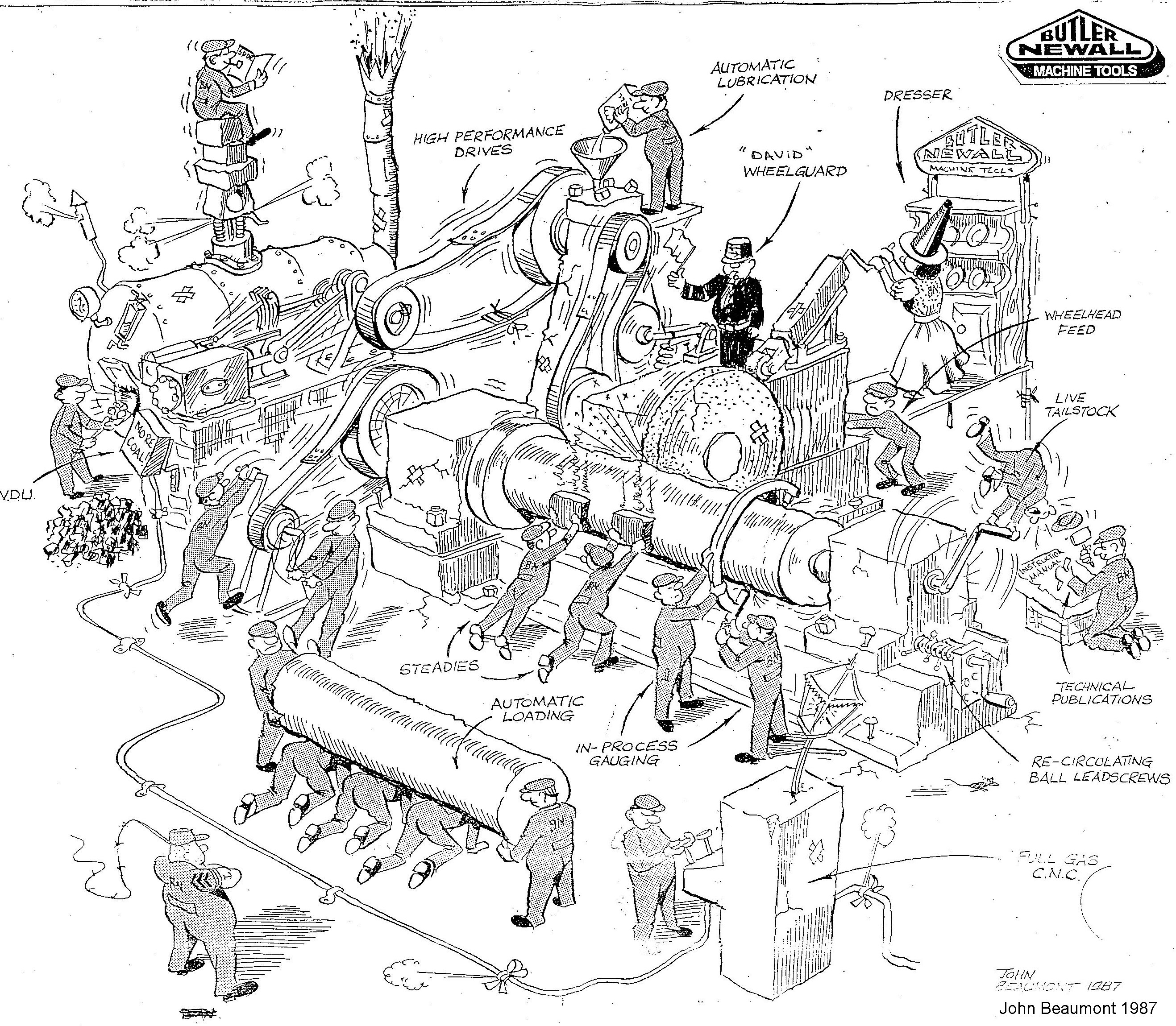
Churchill Roll Grinder – as visualised by John Beaumont in 1987
Churchill Planetary Grinders.
Another Churchill product that transferred to Peterborough was their Model U series Planetary Grinder. A number of these, configured as internal grinders, were produced as part of a Russian contract. They are used for accurate grinding of the internal bores of long cylindrical components, such as heavy gun barrels.
Internal Planetary Grinder
HIGH PRESSURE ABRASIVE BELT MACHINES
Small Machine.
Abrasive belt machining had been around for a long time and was well-known in the areas of linishing and polishing operations. But it became clear that by using modern and more exotic abrasive materials (e.g. alumina-zirconia mineral alloy) on a belt, then by applying that belt to a workpiece under high pressure, extremely rapid metal removal rates could be achieved,
Newall entered this market via an American company, KLK, who made a small abrasive belt grinder that they supplied to Newall mainly for experimentation purposes (although it is believed one or two were sold to customers). It consisted of a belt running around front and rear horizontal rollers, with a pneumatically operated plunger at the front of the machine that could force the workpiece into the belt as it passed over the front roller. A favourite demonstration was to plunge a one-inch (25mm) square steel bar about 4 inches long into the belt and watch the visitor’s reaction as the bar simply disappeared in just a few seconds!
Large Machine.
Based on their experience with the KLK machine, Newall went on to develop a much larger machine which they hoped would have applications in the automotive industry, typically for machining flat surfaces on large components such as cylinder block castings.
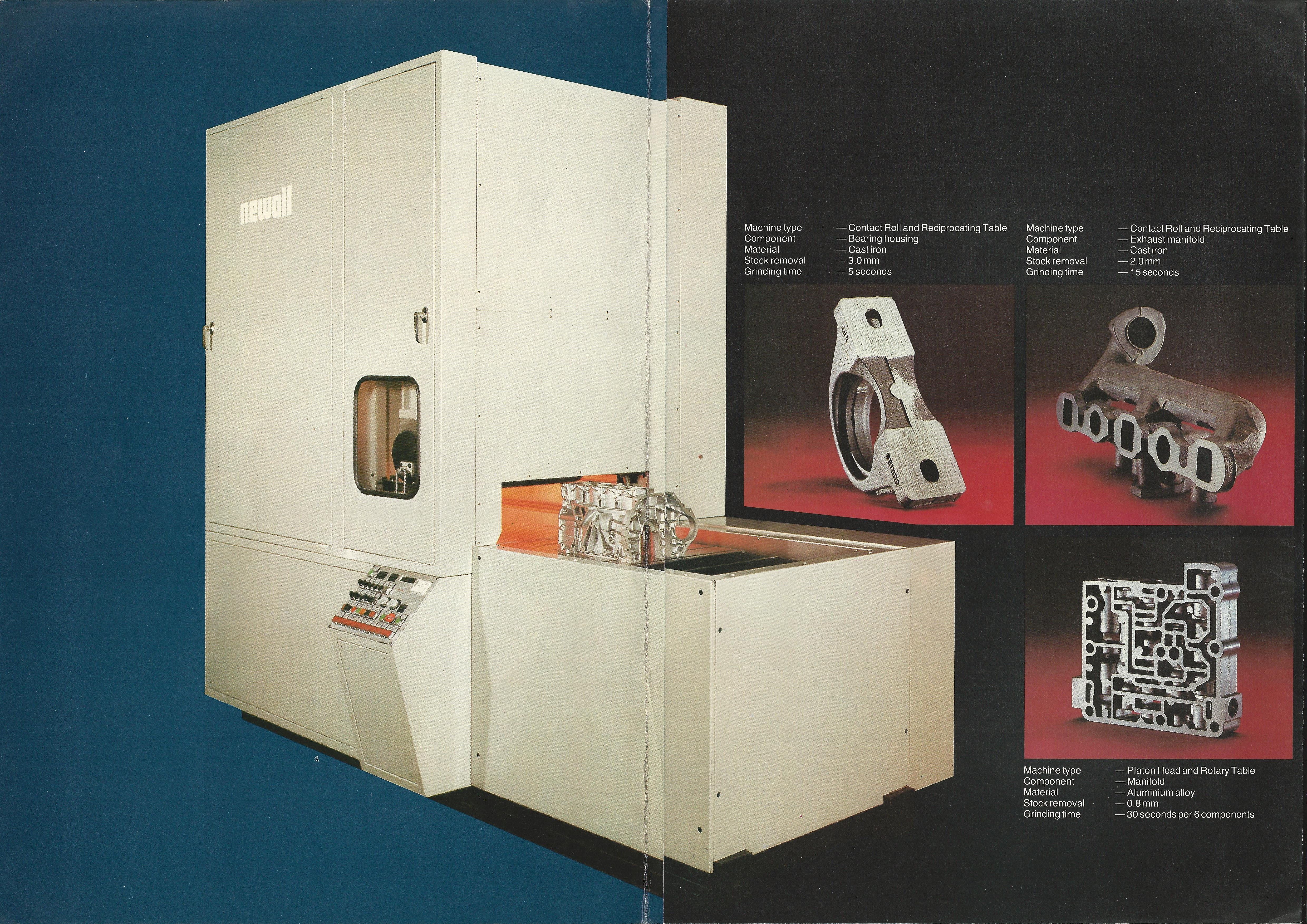
High Pressure Abrasive Belt Grinder
It used a vertical abrasive belt about 600mm wide (from the author’s memory) driven by a 110KW motor on the bottom roller (just visible through the window in the side panel), and a pneumatic tensioning device on the top roller. The top roller could also twist side to side about a central vertical axis by means of a small cylinder and this caused the belt to track from side to side. Photoelectric sensors detected the left-hand and right-hand edges of the belt and kept it more or less central by twisting the top roller in the appropriate direction. Newall took the somewhat strange decision, for an experimental machine, to build a hard-wired control system rather than one based on a Programmable Logic Controller, so that making even small changes to the functionality of the machine could involve many hours of re-wiring.
The workpiece was mounted on a substantial horizontal reciprocating table that would pass it under the bottom roller and back again. This table was supported on four linked screw jacks that could raise it up by means of a DC servo positioning system to apply the cut. So the sequence of operation would be to raise the jacks, feed the component under the belt into the belly of the machine, taking the first cut, raise the jacks again and feed the component back out to apply the second (and probably final!) cut.
As had been shown on the smaller machine, metal removal rates were impressive and the machine was fascinating to watch in action. One problem that was never properly solved was the fact that the belt edge sensors didn’t like being drenched in coolant, and because of the prodigious quantity of coolant that was required, this was always going to be an issue. Although exhibited at MACH 80 (machine tool exhibition) at the National Exhibition Centre in 1980, the machine never went into production and was quietly abandoned, but a single brochure has been unearthed (from which the above photo is taken) and can be downloaded here. The brochure indicates that two basic configurations of the machine were envisaged: the first having a single roller top and bottom (this was the prototype machine), but an alternative would have had a single roller at the top with two rollers and a platen at the bottom (more like a linishing machine), optionally with the component(s) mounted on a rotary table. This latter version was never built.
Exhibiting the machine at MACH 80 brought it to the attention of a Sunday Times industrial journalist and this resulted in a photo-shoot of the machine and its designer at No. 2 factory a short while later.
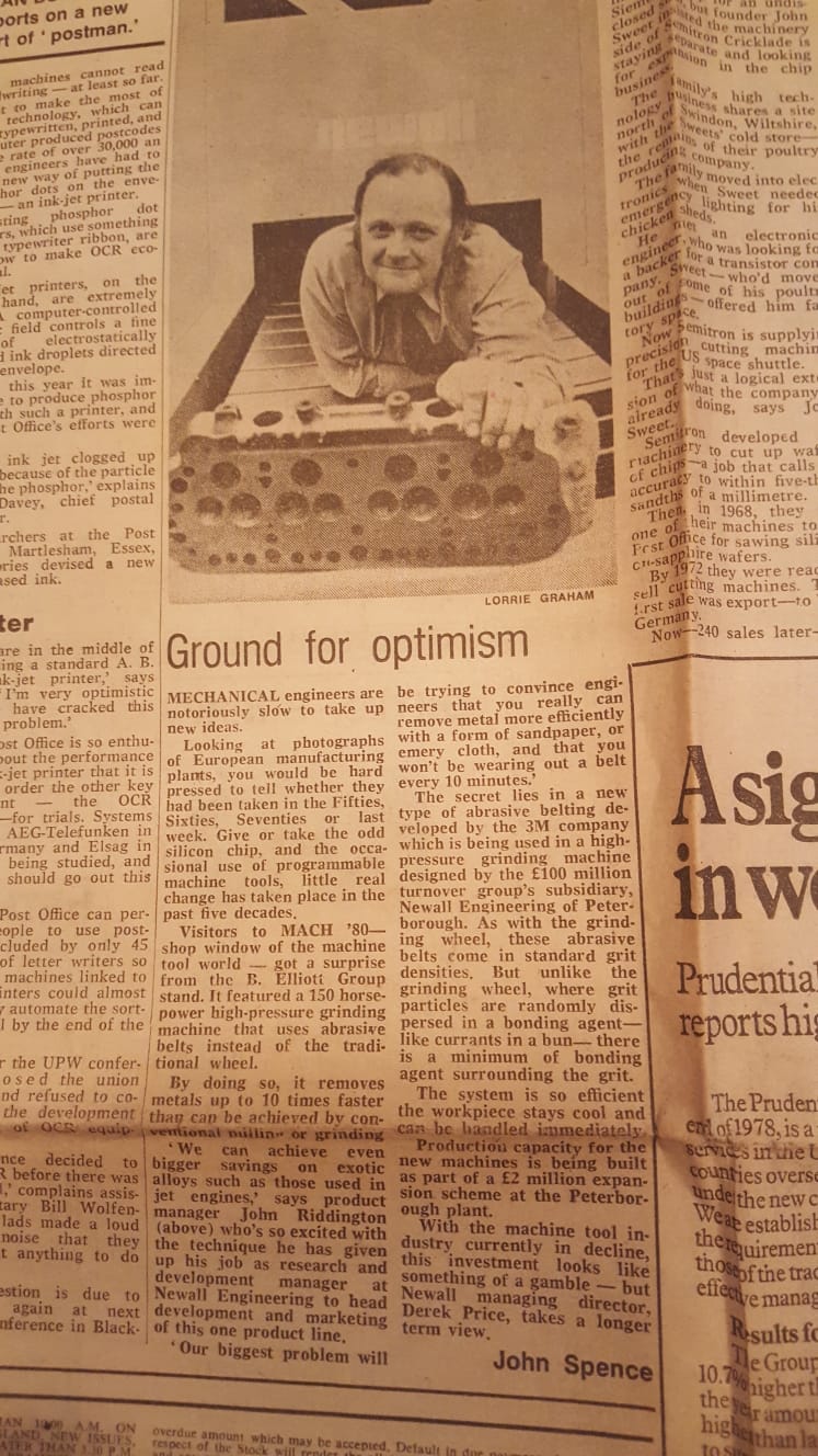
Sunday Times Article
The chosen photographer was an exceptionally glamorous young lady (Lorrie Graham), and as she was escorted through the machine shops to the abrasive belt machine there was a significant loss of production as most staff stopped work to take a good look at this unusual visitor.
She decided it would make a good photo if John Riddington, the machine’s designer, would adopt a prostrate pose on top of the machine bed, looking as if he had just emerged from beneath the abrasive belt. John was horrified by this idea and took a good deal of persuading before he reluctantly climbed up and did as he was bid. The result was preserved for posterity when it appeared in an article in the Sunday Times, and we are able to reproduce it here. (Click on the image to enlarge).
[[P.S. We are saddened to report that John died suddenly in January 2019. The photograph of the Sunday Times article has been retrieved from his personal collection and kindly contributed here by his son, Nick.]]
ELECTRICAL DISCHARGE MACHINES
Spark Erosion Machine
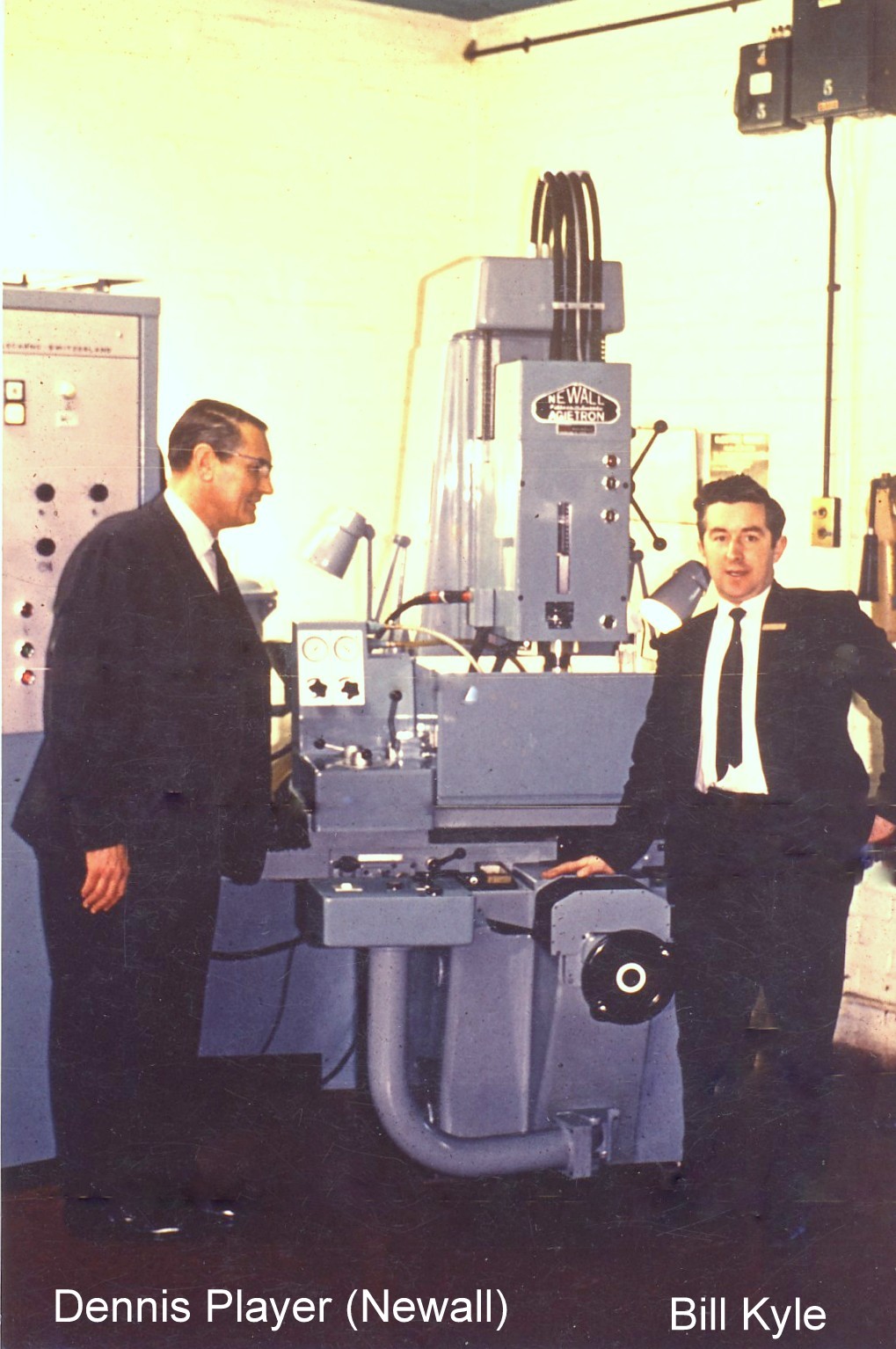 In the mid-1960’s, Newall Engineering and Matchless Machines Limited (MML) undertook a joint development to offer a ‘spark erosion’ machining process based on the Newall range of jig borers. This development used a spark erosion head manufactured by Agie in Switzerland, and the final machine was marketed through MML as the Newall-Agietron. We understand that a total of 7 jig borers (model 1520) were built in 1967 and supplied to MML, where the Agie spark erosion equipment was fitted, commissioned and demonstrated before being shipped to their customers.
While the project was technically successful, it did not achieve its anticipated full potential due (we understand) to the relatively high cost of the Newall machine. Those interested in learning more about electrical discharge machining in general might like to go to our Electrical Discharge Machining page.
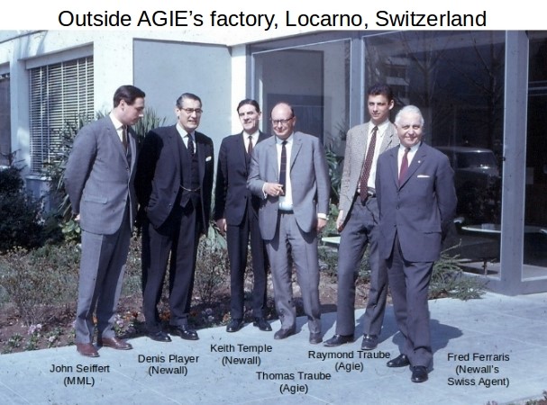
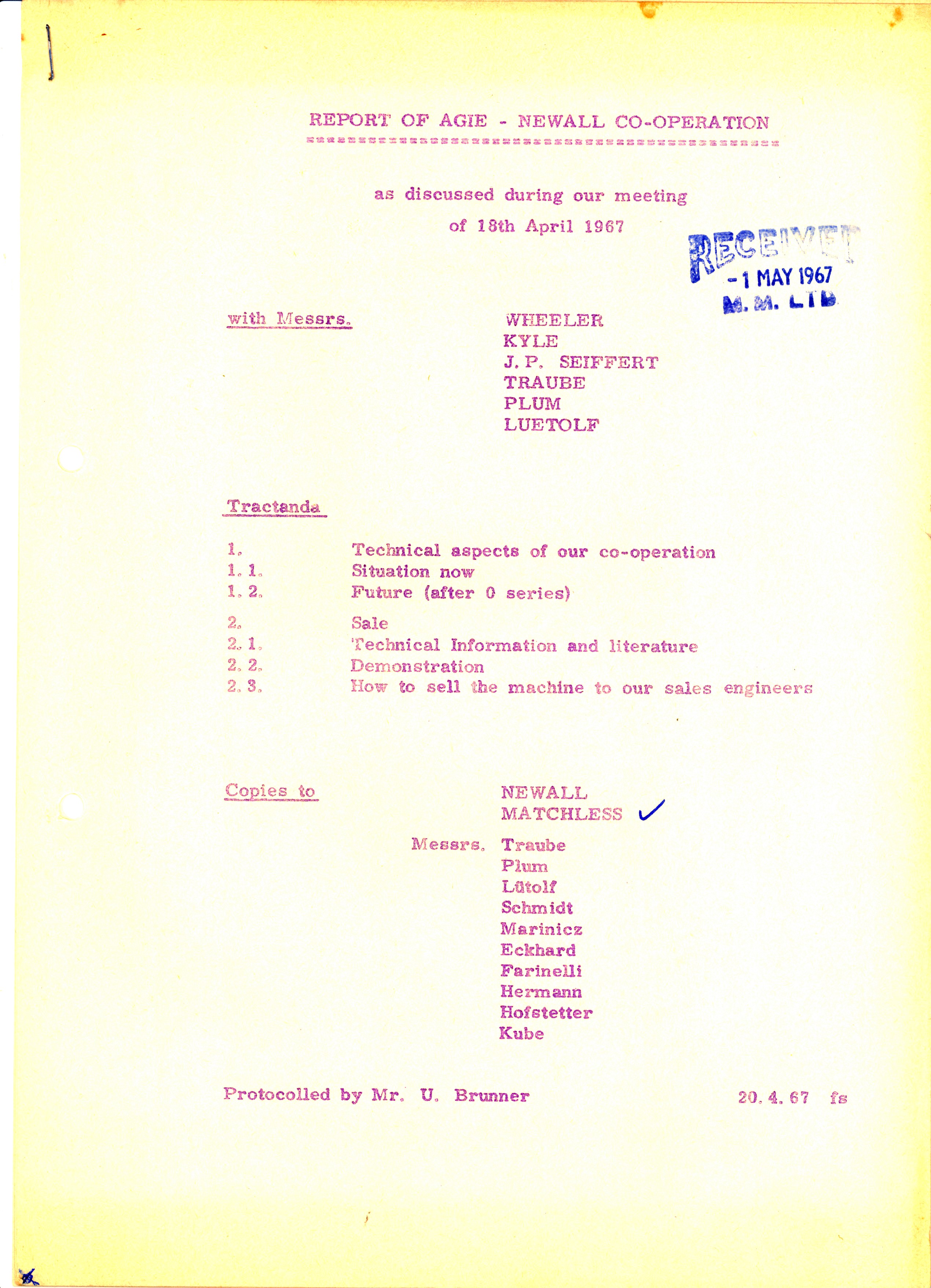
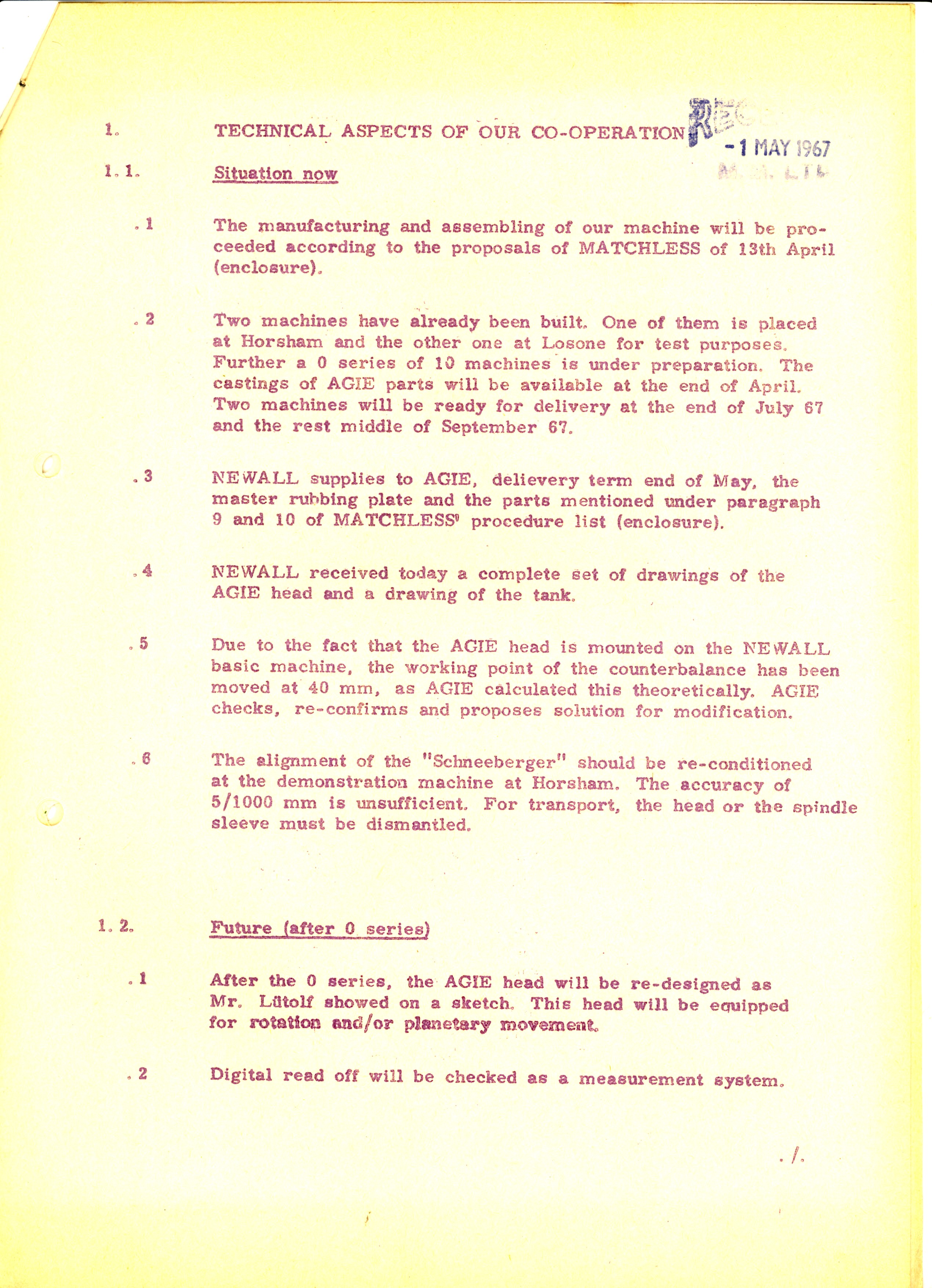
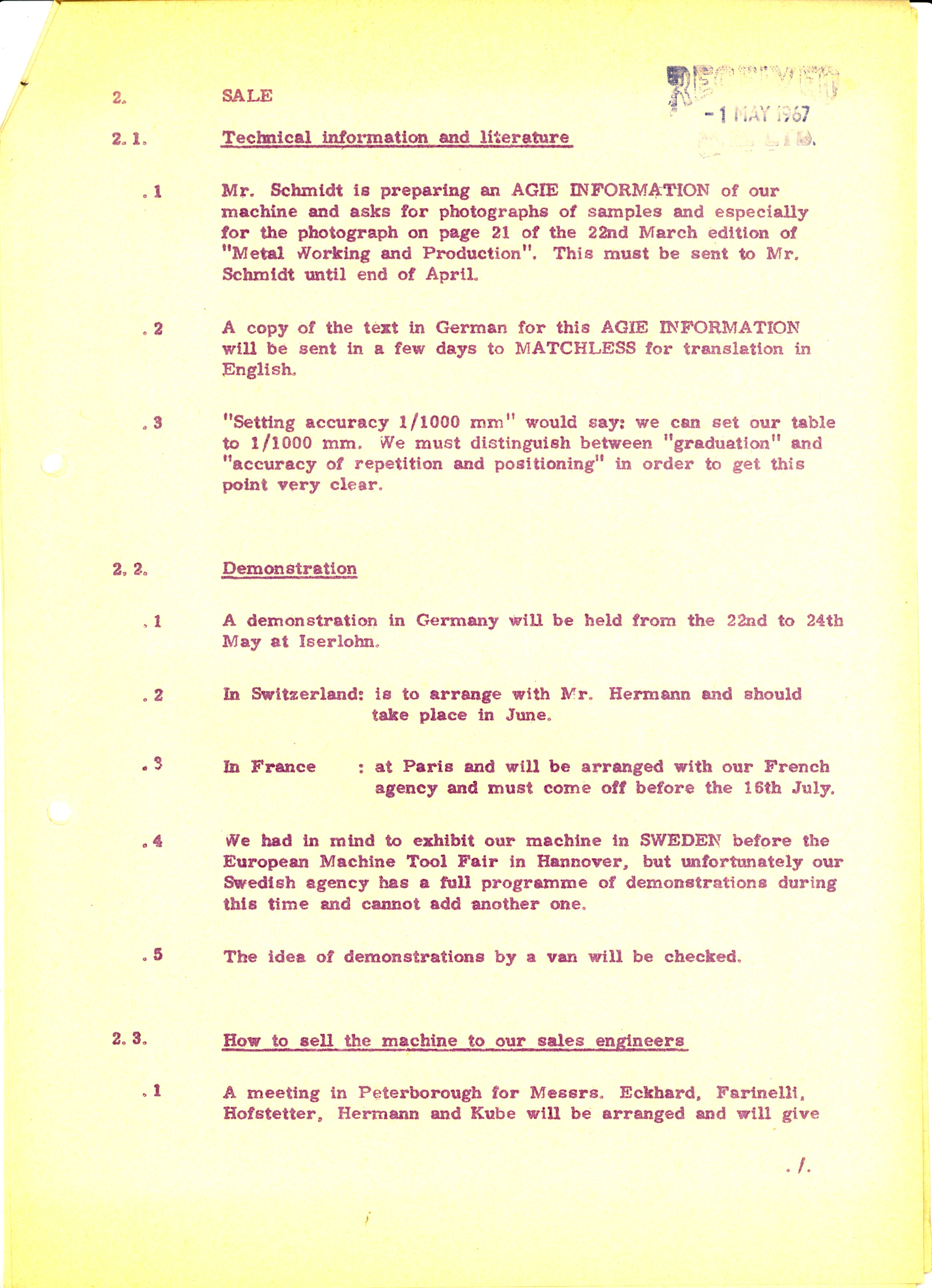
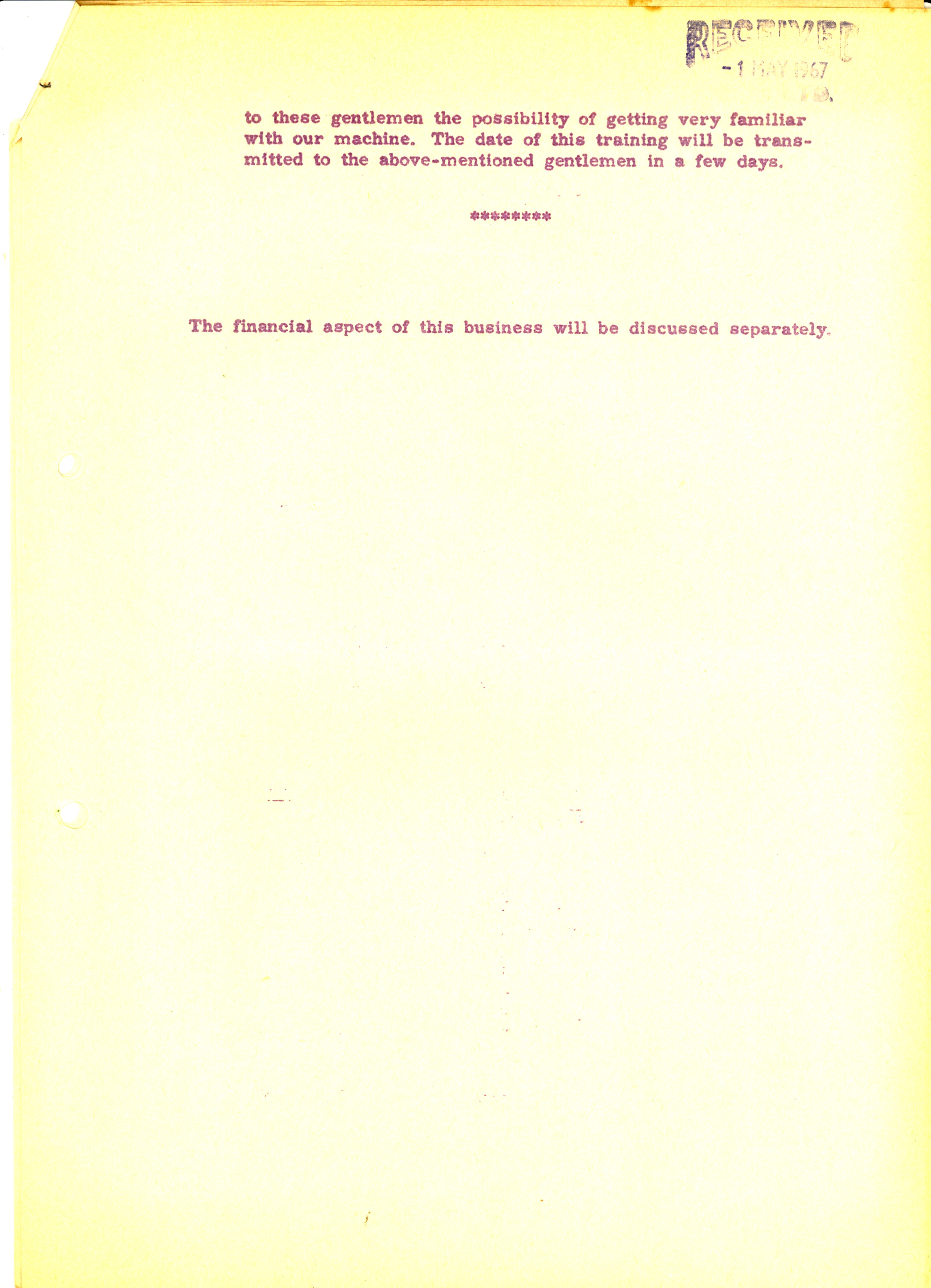
The following 4 images are of a meeting report outlining planned co-operation with MML on a joint project to add spark erosion machining to a jig borer. (Click to enlarge).
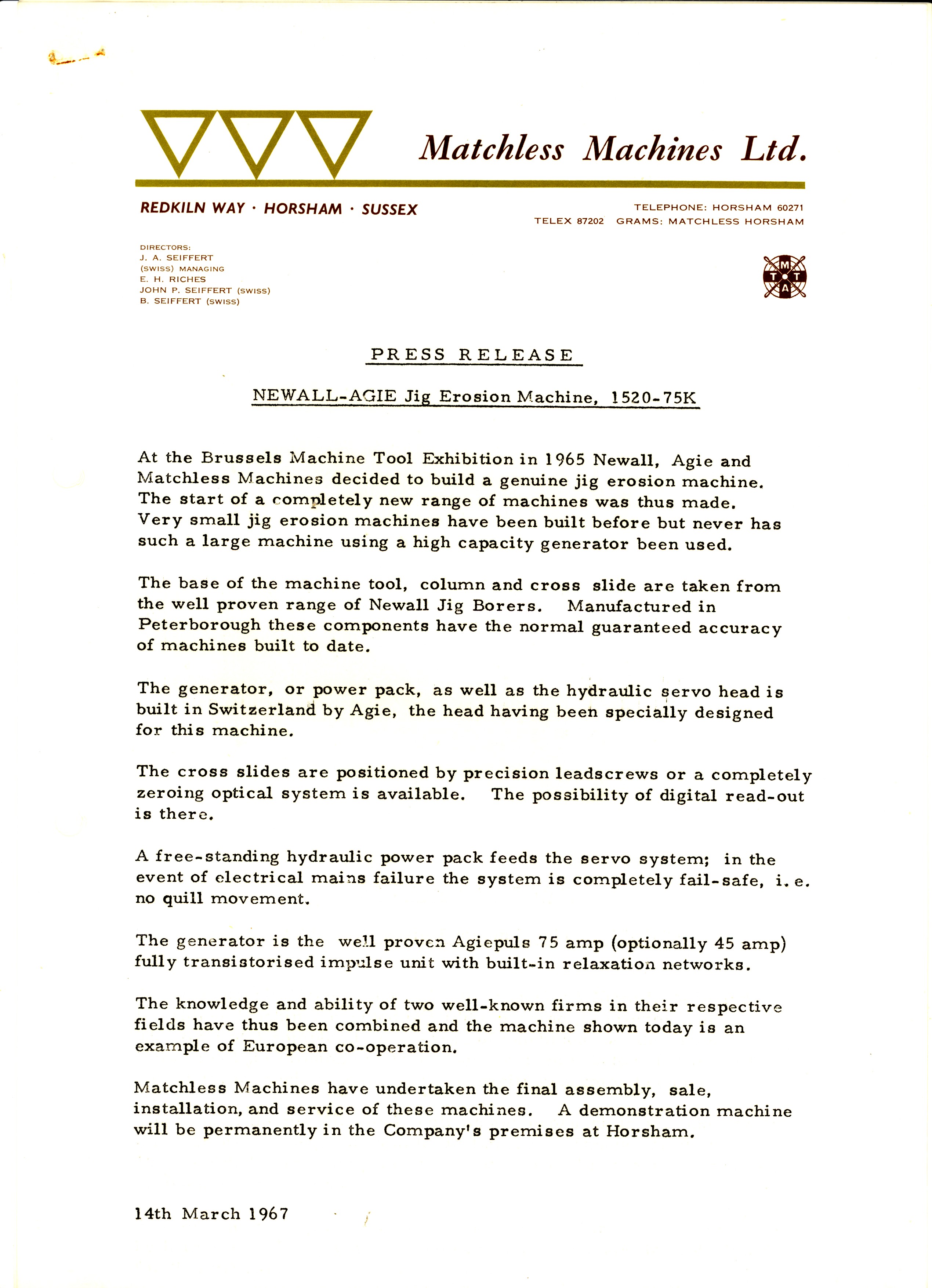
The final 2 images (click to enlarge) show the Press Release and Specification for the Spark Erosion machine: 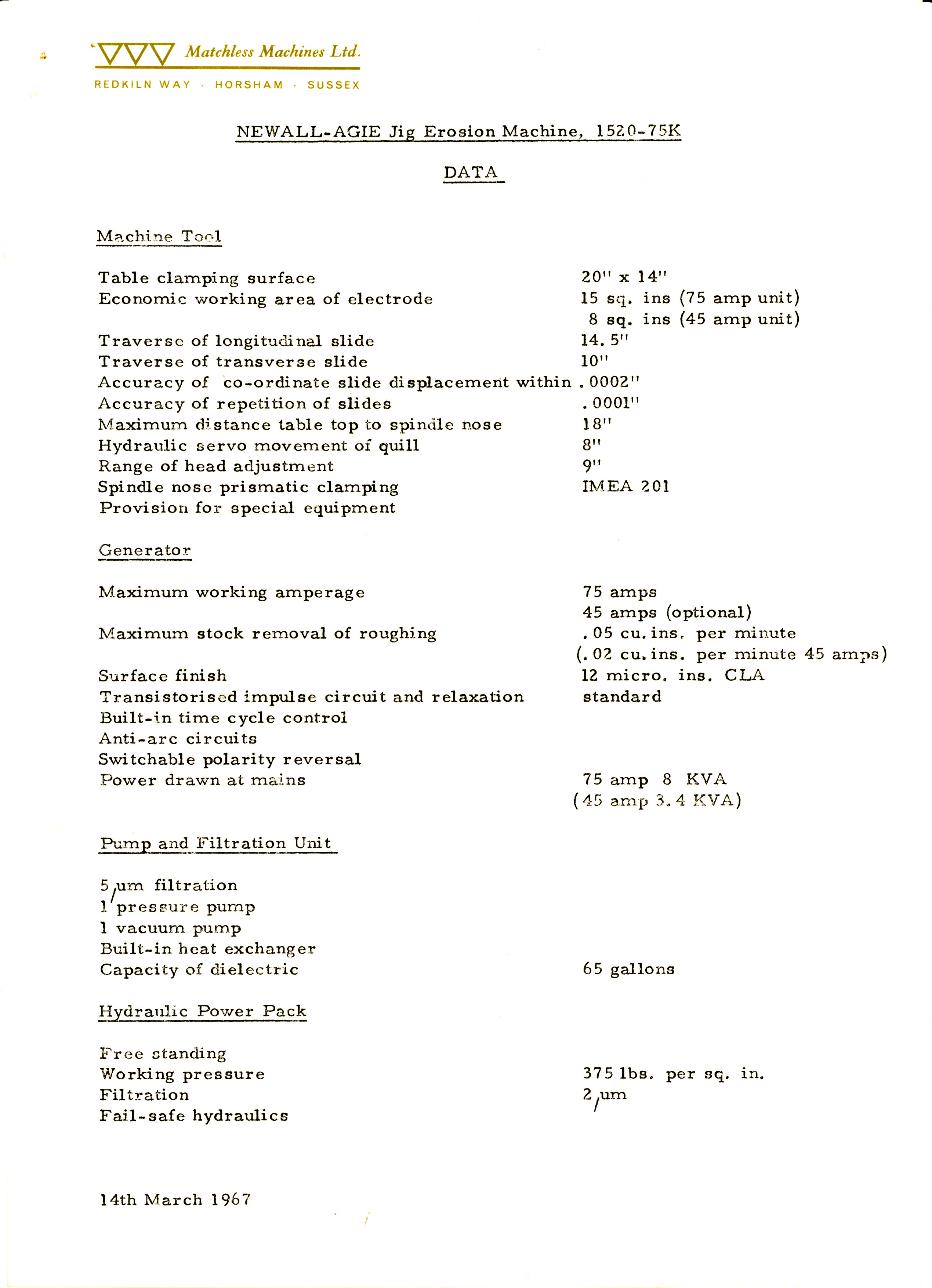
[[We are grateful for this information and photographs which were supplied by Mr John Seiffert, Managing Director (retired) of MML.]]