GRINDING MACHINES
Crankshaft Grinders.
Newall were well-known for their range of crankshaft grinding machines for the automotive industry. They were used all over the world by the leading manufacturers of petrol and diesel engines for the car and truck markets as well as the construction and agricultural sectors.
There are two distinct types of grinding operation required in the production of a crankshaft. The main bearing journals support the crankshaft in the engine and they have to be ground on a perfectly straight axis to ensure smooth running and long engine life. This is achieved by rotating the crankshaft between centres along its primary axis as the journals are ground. The “big-end” crank pins, then have to be ground by rotating them around their individual axes, which is achieved by moving the primary crankshaft axis off-centre by means of “throw-blocks” incorporated in the machine. These two operations, journal and pin grinding, are carried out on two different types of machine, with the journals being ground first.
Newall used large, typically 42″ (1067 mm) grinding wheels running at up to 60m/sec peripheral speed and some machines used a variable speed spindle drive so the peripheral speed could be maintained as the wheel reduced in diameter. To eliminate the possibility of “chatter” during the grinding process, it is important that the grinding wheel is precisely balanced and the Newall machines often incorporated automatic wheel balancing. Several methods were tried at various times, but one of the most successful involved machining 4 hollow chambers in the spindle that could be individually injected with coolant, thus adding extra mass in up to four places. Vibration sensors detected out-of-balance forces and the vibrations were almost eliminated as the anti-vibration control system squirted coolant into the appropriate chambers as determined by a phase sensor. The coolant was kept in place by centrifugal effect while the spindle was running, but drained out as it came to rest. The principle is much the same as a tyre fitter adding lead weights to a car wheel rim to achieve the same result.
Such large and massive grinding wheels rotating at high speed contain significant stored energy representing a potential hazard to personnel, and Newall always paid great attention to the design of guards that were intended to contain debris within the machine in the event of a wheel disintegrating. Testing these guards presented unique challenges and there is an interesting story relating to one practical test that went wrong. It was decided to shatter a wheel deliberately by detonating a small explosive charge buried in the grinding wheel while running at normal speed. High speed cameras would then record the subsequent events. Owing to the nature of the experiment, it took place in a Ministry of Defence bunker in some semi-secret location with everything triggered remotely from a safe distance. The first trial was a flop when the charge proved too small to shatter the wheel. A somewhat larger charge was therefore provided. Unfortunately, and rather spectacularly, not only did it destroy the grinding wheel but it also wrecked the machine and demolished most of the bunker! The company was faced with the cost of re-building the bunker before successfully repeating the test.
Early machines used hydraulic cylinders to feed the wheelhead into the work, with a combination of flow-control valves and timer relays producing the required feedrates and dwells. Final size would be controlled by an in-process calliper gauge, manually or automatically applied during the final stages of the wheelhead feed. One popular such gauging system was manufactured by Marposs, but OMT also offered their Etamic system for a while.
Later machines had programmable electronic control systems and around 1980 Newall embarked on a pioneering project to develop their own control system for grinding machines. Microprocessor-based and using software-defined real-time servo loop closure, these controls broke new ground in terms of features and performance.
Journal Grinders.
Newall produced a range of grinders with a single wheel to grind one journal at a time, with the crankshaft rotating between centres on a table that could index sideways to present each journal in turn to the grinding wheel. Accurate positioning of the table was necessary to ensure that equal amounts of material were ground off both side-walls of the journal and this was achieved by a forked probe unit that would advance and locate on both walls, and which would send signals to the table servo system to achieve a central, balanced position. This technique was sometimes referred to as “spark splitting” as it emulated an earlier manual adjustment that the operator could make while observing that the same degree of sparking was evident from both sides of the grinding wheel.
The machines were fitted with integral dressers to sharpen the wheel as required. These dressers might take the form of a single-point diamond tool following a former as it traversed across the wheel to achieve required profile, a 3-part diamond wheel (click on the image on the right for a more detailed description), or a fully formed diamond wheel.
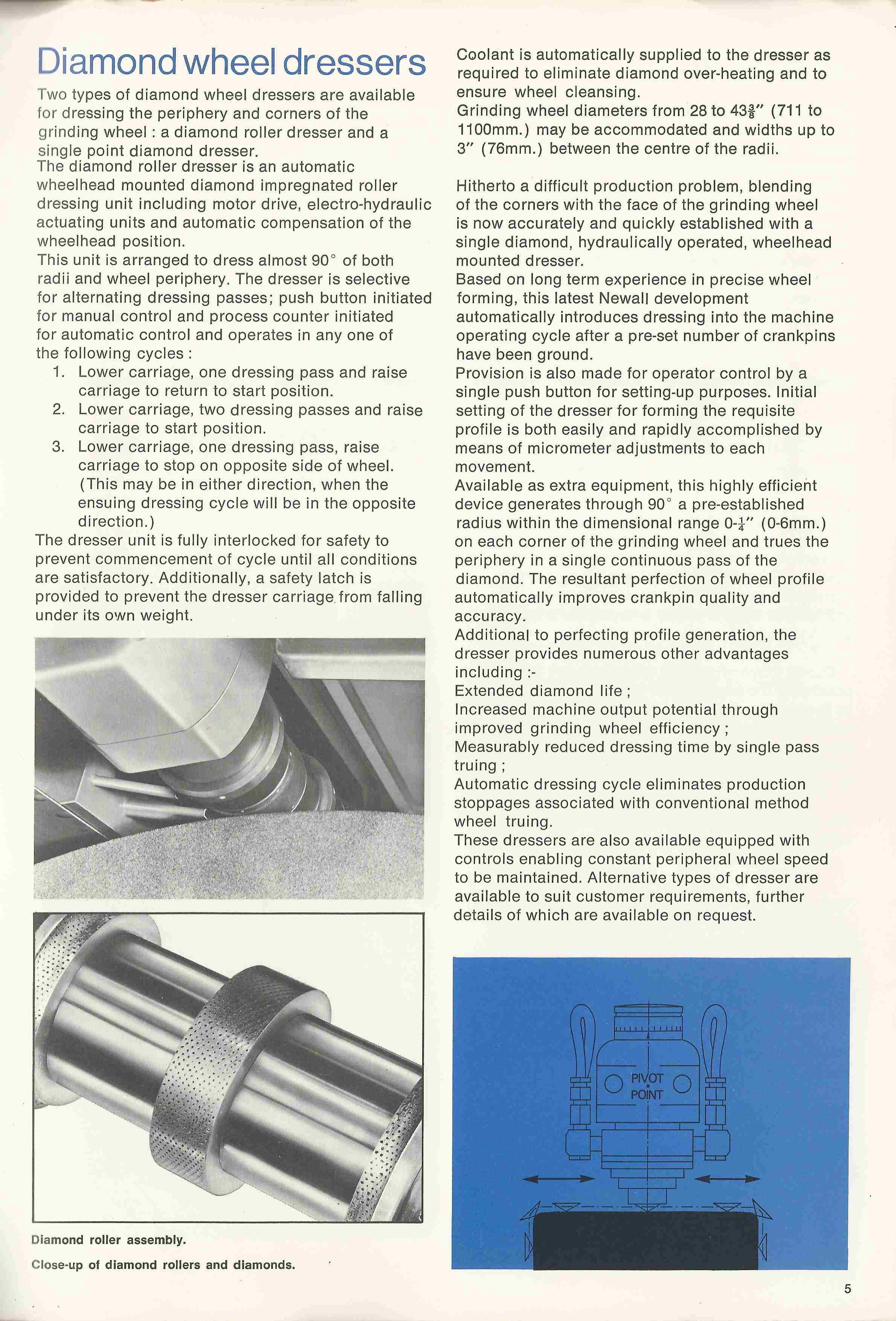
Diamond Wheel Dressers
Clearly, when the wheel is dressed, its diameter is reduced so this has to be allowed for when the control system feeds the wheel in to grind the journal. Final size would usually be confirmed by some form of in-process gauging, directly measuring the actual diameter of the journal by means of a calliper equipped with a suitable measuring device. A popular machine of this type was the “DJ” single-wheel journal grinder, which could be used for both crankshaft and camshaft journal grinding.
For higher production rates, Newall also produced multi-wheel grinders, capable of grinding all the journals in a single operation. The wheels would be dressed by multiple single-point traversing diamond tools (one per wheel) passing across all the wheels before the start of the grinding cycle. Adjustment of the dresser was critical to ensure that all wheels were dressed to the correct size and shape (perfectly flat across the width and the correct radius on each edge).
The spindle assembly when fitted with all the grinding wheels was an impressive sight, as in addition to the main bearing journals, they might also be machining an additional and different diameter for the crankshaft rear flange oil seal. Significantly more power was required to rotate the spindle than on a single-wheel machine and a similar increase in the power of the coolant pump was needed to keep the component properly cooled during grinding.
Because all journals were ground in a single operation, there was no requirement for a traversing table. However, in some cases the table could pivot to compensate for any slight taper across the grinding wheels, with the required movement determined from in-process gauging measurements on the two end journals.
Sometimes, automatic steadies would be provided, which would feed in to support one or more of the journals being ground. A successful machine of this type was the “MJ” multi-wheel journal grinder.
Click on the image below to see an MJ machine, installed at the Ford Cleveland (Ohio) plant in 1985, being loaded by an overhead gantry type automatic loader.
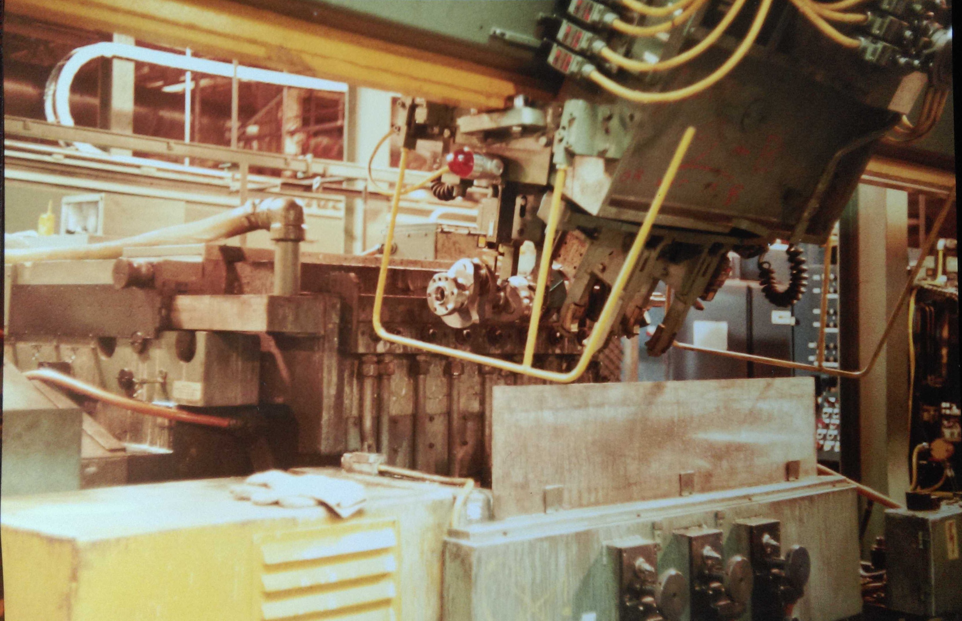
Loading an MJ – Ford Cleveland
This was an 8-wheel machine (7 journals for a 6-cylinder crankshaft plus the flywheel flange). In this photo the loader has a new crankshaft in its jaws ready for placing into the machine once the empty jaws have gone down and retrieved the finished crankshaft from the machine.
You can see the vertical pipes supplying high pressure coolant to the individual wheels The single large pipe feeding into the top of the coolant manifold gives an idea of the volume of coolant that was required. Finally, the black adjustment hand-wheels in the front of the machine are part of the three stepper-motor-driven steadies that were fitted on this machine.
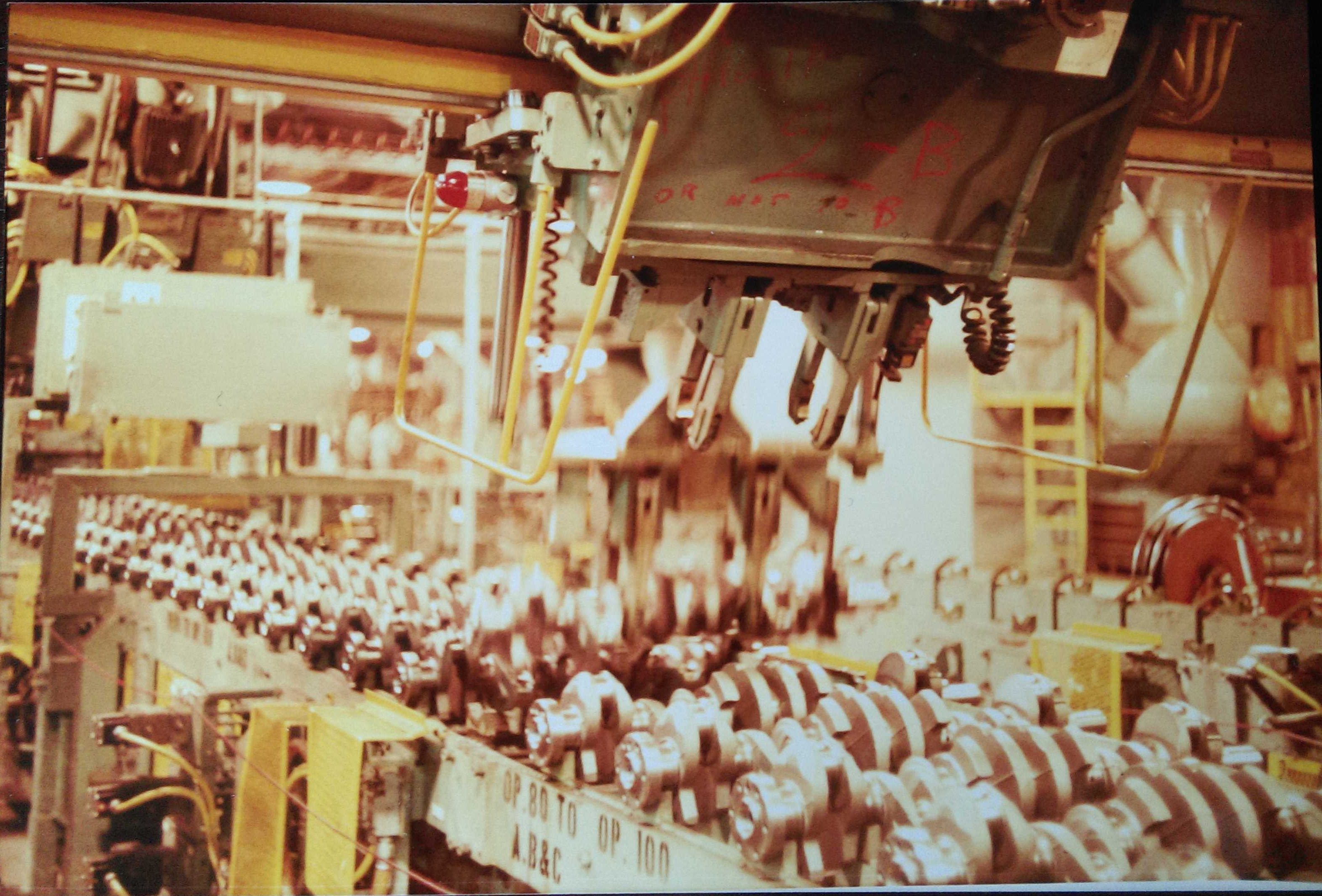
Crankshaft Production Line – Ford Cleveland
In this installation there were two MJ machines, each served by this single gantry loader, which received its supply of parts from a walking-beam conveyor alongside (see image at right). In this photo, the loader has placed a finished component on the out-feed part of the conveyor and has been caught in the process of picking up a new crankshaft from the in-feed part, ready to transport it to the grinder.
Pin Grinders.
Grinding the crankpins was done with the crankshaft located accurately and positively on its end journals in the machine’s “throw-blocks”.
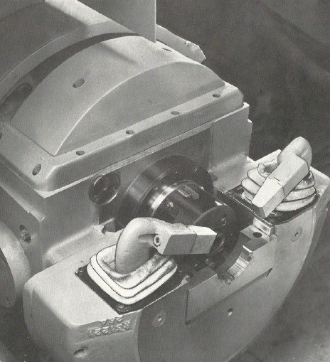
Throwblock
These clever mechanisms allow the crankshaft to be rotated around the centre-line of each crankpin in turn, by off-setting (or “throwing” off-centre) the crankshaft primary axis. Crankpins would usually be ground one at a time on a single-wheel machine (clearly they can never all be done at once because they don’t share a common axis, although in some applications twin-wheel grinders have been tried), so a traversing table arrangement is needed to present each pin in turn to the grinding wheel and this would again be fitted with a “spark-splitter” probe and sensor mechanism. As for the journal grinder, the machine would typically be fitted with an automatic wheel dresser, balancer and in-process gauging, and might also have in-process steadies to support the journal during grinding. A typical machine of this type was the “DP” crankpin grinder.
Camshaft Grinders.
Newall automotive camshaft grinders were almost as well known as their crankshaft grinders, so both types of machine would often be found in the leading car and truck engine factories around the world. Whereas a crankshaft consists of main journals and pins, so a camshaft consists of main journals and cams, and frequently (in those days) an eccentric for driving a fuel lift pump. The journals would be ground first on a journal grinder, with just the cam forms being machined on the camshaft grinder. The table holding the camshaft could move laterally to present each cam in turn to the single grinding wheel.
To grind a cam form, the cam surface must move towards and away from the grinding wheel as the camshaft rotates about its primary axis. This can be achieved in a number of ways, but Newall favoured the rocking table arrangement, whereby the camshaft rotates in a sub-table that can rock to and fro synchronously with the camshaft rotation in order to generate the cam form. The grinding wheel can then move forward towards the camshaft in order to apply a cut. Some machines varied the speed of rotation of the camshaft during each revolution in order to maintain a near-constant surface speed to aid the grinding process. This required a transducer to monitor the camshaft angular position so the rotation could be adjusted according to how “steep” the cam profile was at any given angle. Lateral positioning of the table is not so critical as on a pin grinder because the grinding wheel is usually wider than the cam and overlaps at each side. Optionally, a mechanism was available to oscillate the grinding wheel from side to side to equalise wheel wear and produce an improved finish.
These earlier machines used a set of master profiles. The master cams rotated synchronously with the rotation of the camshaft being ground, and a ‘follower’ on the master cam was linked mechanically to the rocking table to create the required form on the cam shaft. While this method was successful at the time, it had the significant disadvantage that the form could not be modified without the significant cost and time involved in producing a new master.
In 1981/82 Newall adapted their own control systems experience that had been gained on the crankshaft grinding machines and applied it to cam grinding. The rocking table mechanism was modified to be driven by a high-performance servo motor, which was driven cyclically forward and back to rock the table towards and away from the grinding wheel, its position being locked electronically to the angle of the cam as it rotated. The cam forms themselves (angle and lift at one degree intervals for inlet and exhaust cams) together with eccentric, table position and wheel feed parameters were entered onto a computer. The data was then pre-processed to provide constant surface speed of the cam at the contact point with the grinding wheel, and to calculate the form for each individual cam along the shaft. The complete data for a shaft would then be transferred to the machine electronically when required. For the first time, this system paved the way for truly flexible and comprehensive capabilities that would revolutionise camshaft grinding operations.
The prototype machine (later to become known as “Camtronic”) was exhibited in Chicago in 1982 and took the show by storm, with huge numbers of visitors clamouring to get a glimpse of this new and exciting technology. Unfortunately, during the mid 80’s, the company was facing significant problems, and the failure to develop the “Camtronic” further meant its future was limited.
Jig Grinder.
Newall produced a jig grinding machine based on one of their standard jig borers, where instead of the standard spindle/quill assembly, it was fitted with a precision grinding spindle. Jig grinder spindles run at very high speed (typically 30,000rpm to 60,000 rpm, but occasionally as high as 175,000 rpm) and in the case of the Newall machine, the spindle was rotated by a special electric motor and high frequency inverter drive of Swiss origin. Regrettably, we have no further details of this machine at present.
Creep Feed Grinders.
When the Snow company joined the group they brought with them a new area of expertise, namely creep-feed surface grinding. They had invested significantly in developing this technology and had sold a number of small machines.
Creep-feed surface grinders were designed to take very heavy cuts using a profiled grinding wheel so that finished components could be produced in just a few passes. Indeed, it was envisaged that in some cases, only a single pass would be required. They were ideally suited to producing flat components in hard materials typically with slots or channels running along their length, or solid components of complex cross-section.
The process relied upon the grinding wheel being dressed continuously whilst grinding so that the wheel was always sharp and could remove material at unprecedented rates. A full-form diamond roller dresser was employed, which had the same profile as the required finished component cross-section. During use, the dresser would feed slowly but continuously into the wheel to keep it in prime condition. To compensate for the reduction in diameter of the grinding wheel, the feed axis had to advance continuously at the same rate, in order to maintain the grinding edge of the wheel at the same position relative to the component being machined. Somewhat higher spindle power was necessary to achieve the greater metal removal rate, and great attention had to be paid to a high pressure coolant system to keep the workpiece cool and the grinding wheel clear of debris and swarf.
Newall embraced this new process enthusiastically and embarked on the design of a new and significantly larger machine in the year leading up to the 1982 Chicago Machine Tool Exhibition, where the machine was to be unveiled. It was to be fitted with a variant of the control system Newall had developed for the crankshaft and camshaft grinders, and would incorporate at least two novel features (at that time), namely context-sensitive “soft keys” labelled on the display screen and adaptive feedrate control. The first feature significantly reduced the number of operator control pushbuttons and switches needed for operating the machine. The second was intended to have the machine automatically modify the feedrate parameters chosen by the operator, in order to achieve optimum performance by, for example, “tweaking” the feedrate as necessary to maintain a particular spindle power.
Although the prototype machine was built, and did go to Chicago, unfortunately there had not been time to test (or even complete the software for) the control system because the engineering team was fully occupied making last-minute changes to the systems on the crankshaft and camshaft grinders, which were more important products for the company. So the machine was put on show but was not operational. One memorable moment for the author came when a Newall salesman explained to a potential customer that the machine could not be demonstrated in public because it was all “far too secret”! Subsequently, some progress was made, but the development was never completed and the project foundered.
High Speed Grinders.
Newall experimented with high speed grinding (i.e. high surface speeds of the grinding wheel) in the 1970’s, with a lot of development work done on a cylindrical grinder with a very wide grinding wheel that could be used to finish-grind traditional lawnmower cutting cylinders, as well as other, more exotic components. As a safety measure in case of a wheel breaking free from the machine during development, a large fabricated steel guard, faced with thick plywood was positioned in front of the machine and bolted securely to the floor. This made office staff feel safe until someone did some calculations on how much energy was stored in this massive grinding wheel when rotating at high speed. It was estimated that the wheel would exit the machine, pass through the plywood and steel guard or simply knock it flat, then make its way through the adjacent office before exiting the factory, punching its way into and out of the building next door, before coming to rest somewhere in the scrapyard beyond! The benefits of having the floor-mounted guard were therefore deemed negligible and it was removed.