[[The information on this page was updated in December 2019. We are indebted to Nick Lynch who was previously employed by the company in the drawing office. Nick provided much of the information relating to this company for the period from 1980 until the factory closed.]]
Important Note. Please be aware that we are unable to provide Service Manuals, Operating Instructions, Assembly Drawings or Electrical/Hydraulic/Pneumatic Schematics for any of the machines and instruments manufactured by the Newall Group; we simply do not have access to them. We are unable to help with the repair, refurbishment or operation of any of the products. All the data that we hold is available for free download from the “References” pages that can be found within the relevant sections on the Companies/Divisions tab.
Keighley Grinders (Machine Tools) Ltd was registered with Companies House on 23rd May 1942. Its Memorandum and Articles of Association were registered in June 1942.
As stated in Memorandum of Association, the company was formed “following an agreement already prepared and expressed to be made between Quality Machine Tools Limited and its Liquidator” to carry on “the business of machine tool manufacture” formerly carried out by that company “at Aireworth Works, Keighley, Yorkshire.”
The new company issued a statement of Nominal Capital of £40,000, divided into 80,000 “A” shares at 5/- each, and 20,000 “B” shares at £1 each. The company is registered as a Private Company, and accordingly, shares will not be available for public subscription.
The directors of the new company were Sydney Player, Kenneth Edward Summers, and William James Fouracre. All directors must hold (in their own name) shares to the minimum value of £100, and this holding must be acquired within 3 months of appointment as a director.
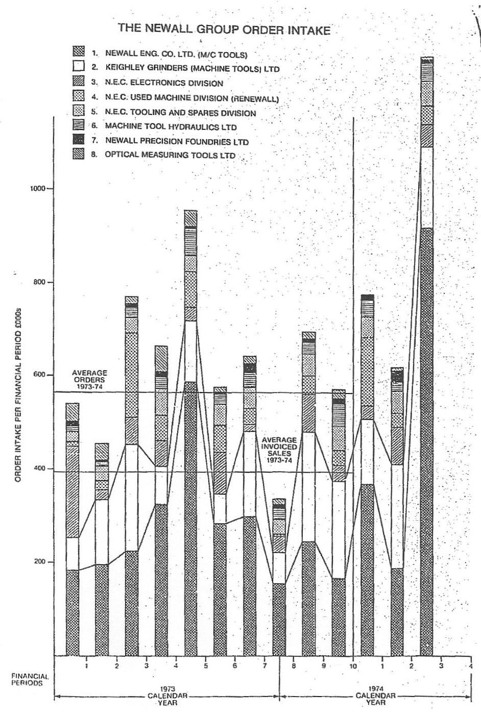
Keighley Grinders became a significant part of the Newall group, as demonstrate by its 2nd position in the Group’s order intake chart for 1973 and 1974 and as published in the Newall Machine Tools’ Report & Accounts for the year ending March 1974. Note that in four of the periods shown on the chart, the order intake for Keighley Grinders equalled or exceeded that for Newall Engineering.
In the mid 1980s, following the closure of the Newall factories in Peterborough, the manufacture of machines from the Newall range was re-located to Keighley. In 1988, the remaining Newall design and drawing office functions also moved to Keighley. Sales and manufacture of these (mainly automotive) products appeared to cease soon after this move, and the Keighley company concentrated their development and production on their range of aerospace products.
During the late 1980s, the company produced [[we believe, quarterly]] a newsletter for all staff. In addition to the general interest information in these documents, there are additional details relating to the company’s problems, and the management plans to alleviate these difficulties. These documents, entitled ‘Kephax’, for Autumn 85, Spring 86 and Spring 87 can be viewed by clicking the links.
Refer to our ADDENDUM page for more information relating to the Newall and Keighley Grinders business after the closure of the Peterborough operations.
Factory:
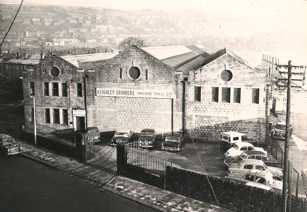 The photograph on the right shows the factory in Aireworth Road. There are 4 bays, though only the 3 main bays are shown clearly in this photograph (bay2 on the left with bays 3 and 4 to the right) . Bay1 is hardly visible in this photo, and is set back and to the left of bay2.
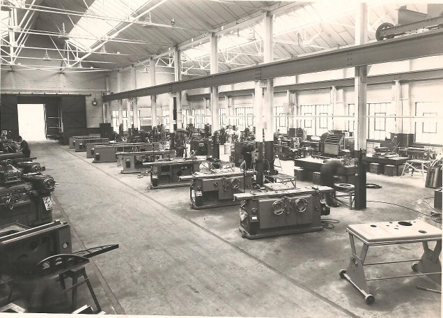
On the left is a photograph of the machine assembly area (nearest the camera), with the sub-assemble (mechanical, pneumatic and electrical) beyond. This photograph was taken from the front (Aireworth Road end) of the bay.
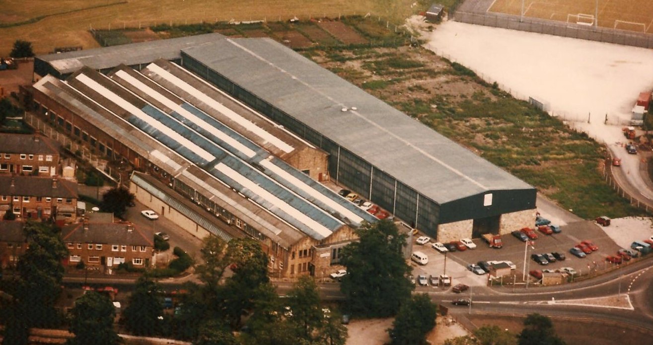
Following the take over of the Newall group by B Elliott in 1977, the Keighley factory was extended by the addition of a new (much larger) bay.
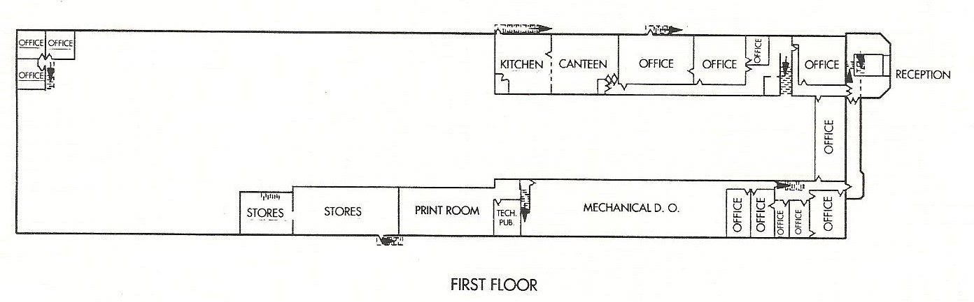
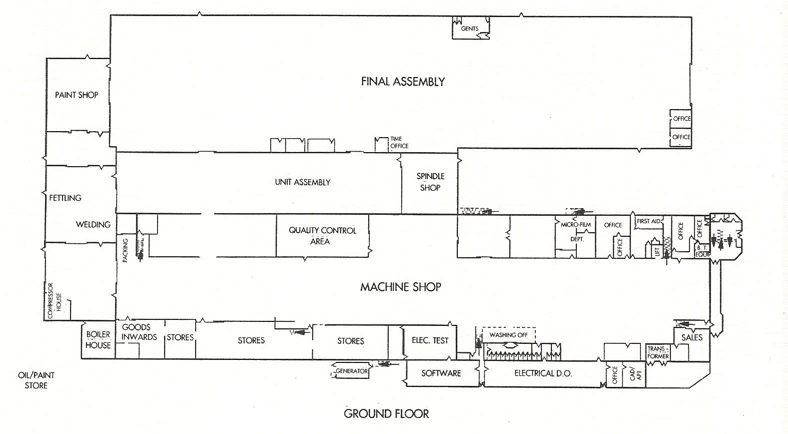 A factory layout plan following the addition of the new bay is shown here.
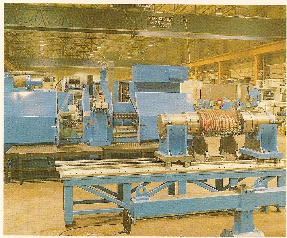
The view on the left shows a new blade tip grinder machine being assembled in the new bay.
The photo below, from James Rye, is a view of the Software Department.
Products:
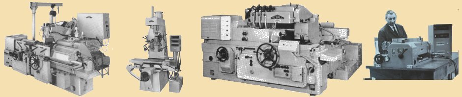
During its early years, the company manufactured a range of small general purpose grinding machines. These included:
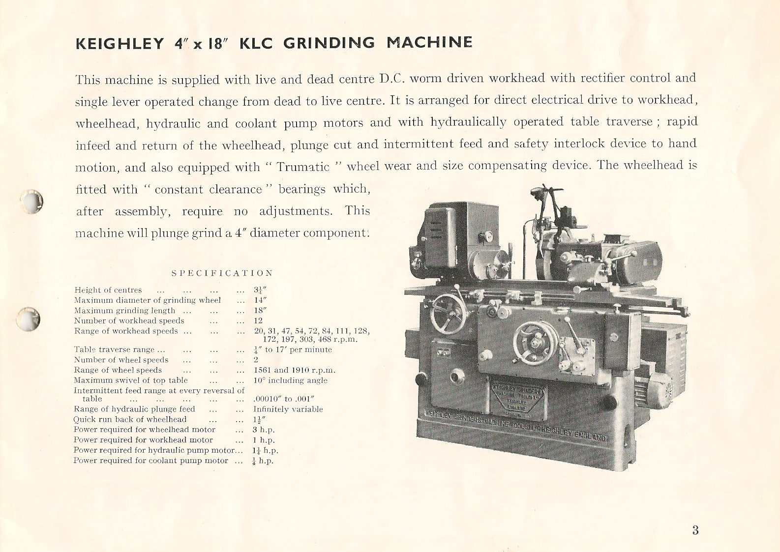
the KLC grinding machine
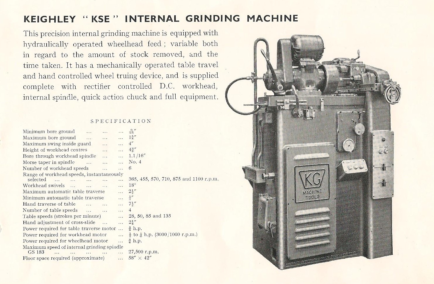
the KSE internal grinding machine
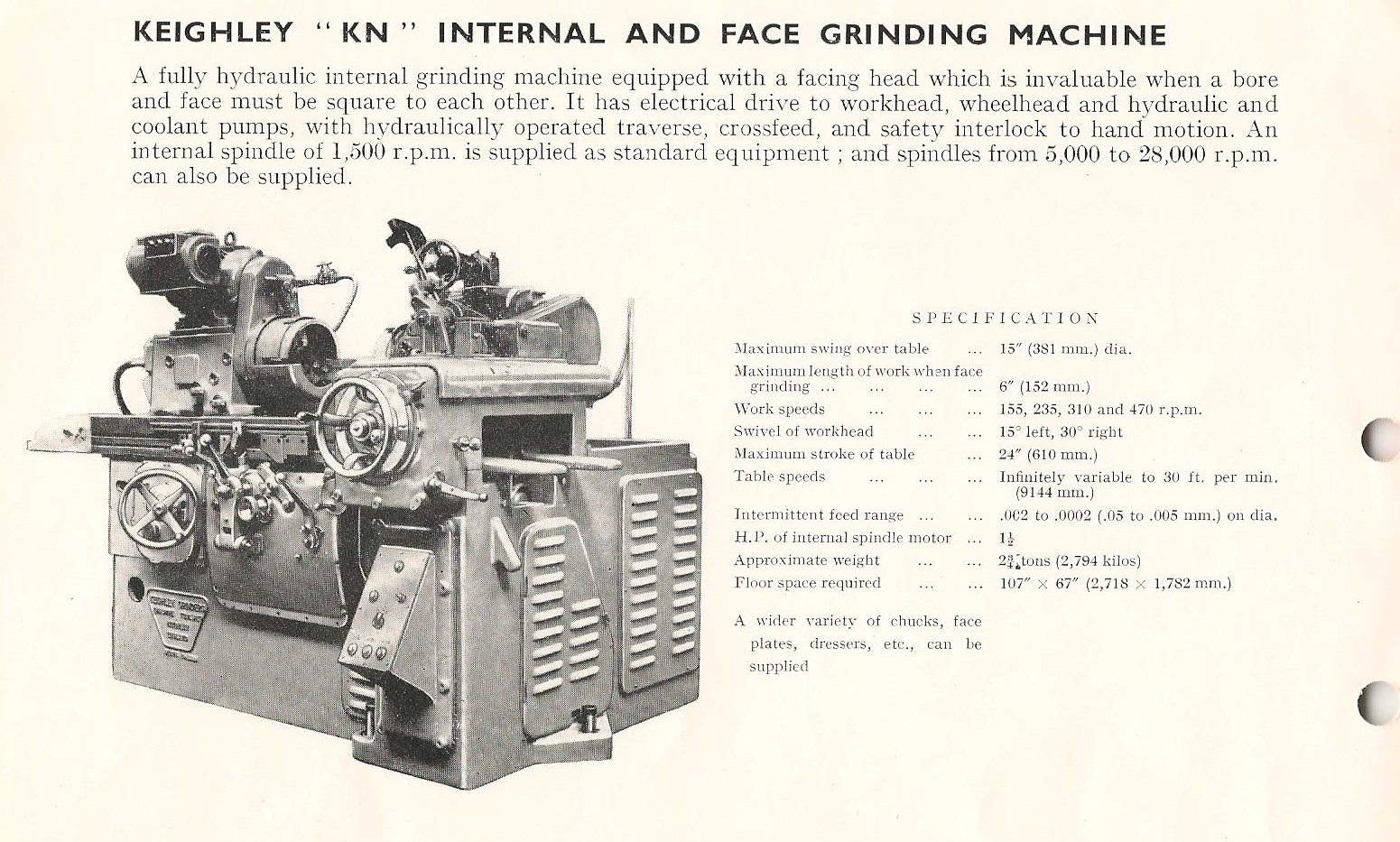
the KN internal and face grinder
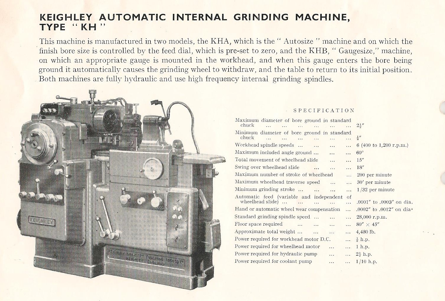
KH automatic internal grinder
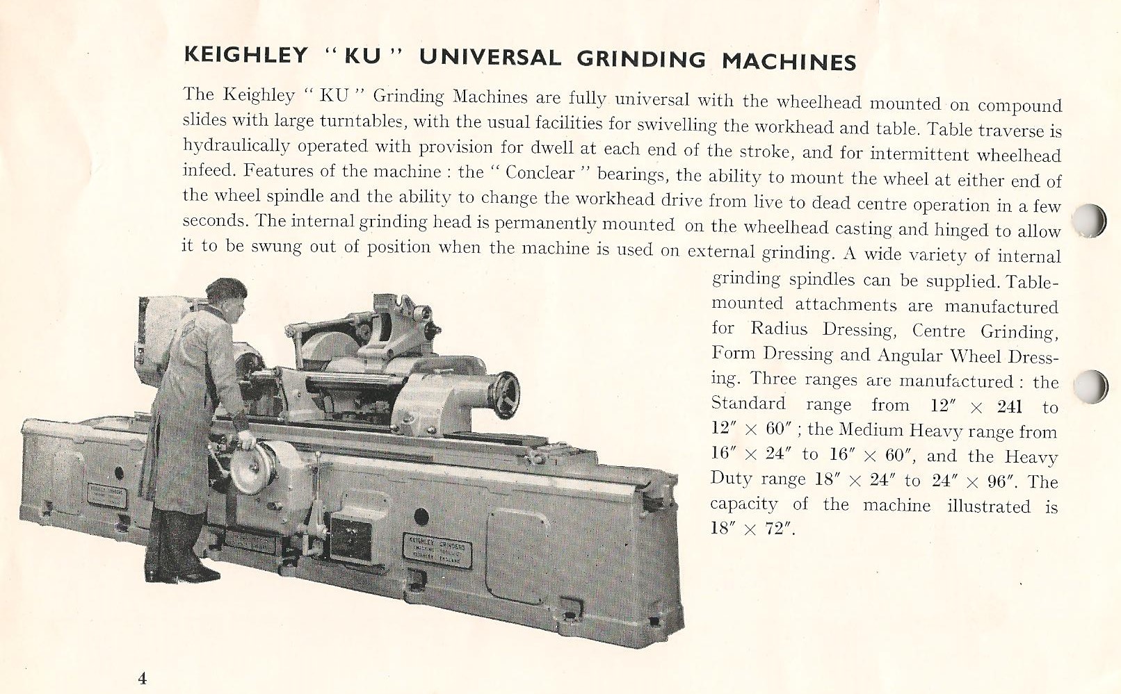
KU universal grinder
Later, in mid 1970s, new developments saw the introduction of proprietary CNC (computer numerical control) KG300 grinding machines. These were fully enclosed machines intended for high levels of production. Further developments resulted in a new range of CNC machines to include the CNC 500, CNC 600, CNC 1000, and CNC 1500. which are all featured in a sales brochure entitled ‘High Technology Grinders‘.
For all these CNC systems, the company’s policy was “to aggressively pursue proprietary systems thereby giving the company and its customers access to continued hardware development. Application specific software was developed in-house by a team of dedicated engineers, whose detailed knowledge of the process and machine tool dynamics enables them to provide the optimum control solution.“
In the late 1970s and 1980’s, new products were developed specifically for the aerospace industry. These included the Blade Tip Grinder, and the Gap Bed Grinder as detailed below.
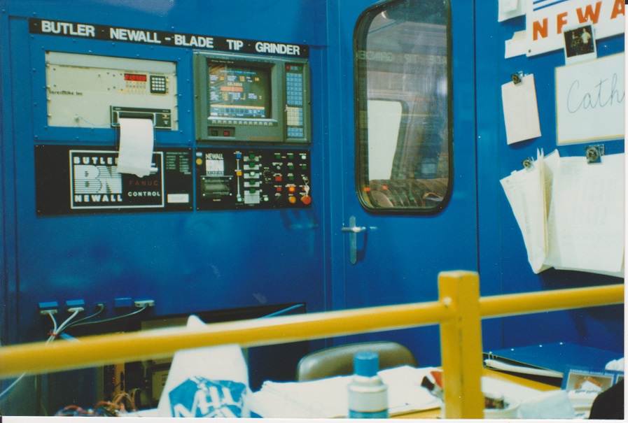
BLADE TIP GRINDER
“Today’s generation of high by pass ratio gas turbines, as produced by major manufacturers throughout the world, rely on tight tolerances between the compressor and turbine blade tips, and the engine case to produce a gas seal thereby maximising compressor and turbine performance.
“The design of the compressor rotors in particular is such that each individual blade is a loose fit within a stage, thus permitting expansion under operating conditions.
“The Challenge. Grind each blade tip, and hence each stage, to a specific size so that under operating conditions the performance of the whole compressor is maximised. In addition, produce in graphical and numerical form the results of a series of measurements to confirm the size of each blade, the maximum, minimum, and average size of the blades within a stage, the size of the lands and or the seals between the stages and, in certain cases, compute the compressor efficiency under operating conditions.
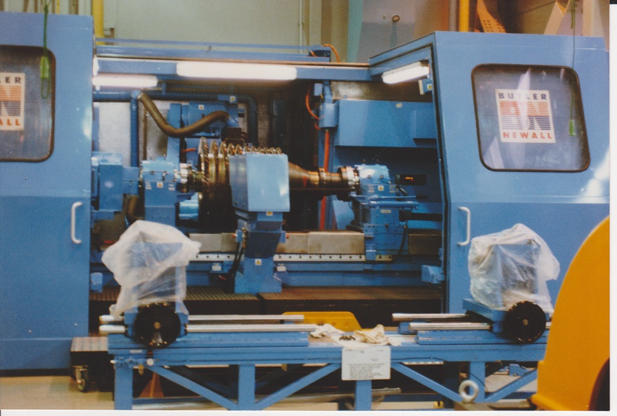
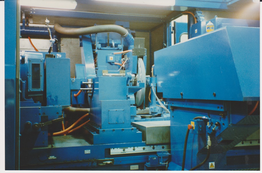
“The Solution. Securely hold the compressor and rotate it about its centre line at a speed sufficient to ‘lock’ the smallest blades into position and withstand the force applied by the grinding wheel. Equip the machine with a laser, to count and measure each blade, as well as a touch sensitve probe to measure the lands or seals. Format the software in such a manner that the machine will grind and measure the blades at the same time and print out the results together with the efficiency calculation as required.”
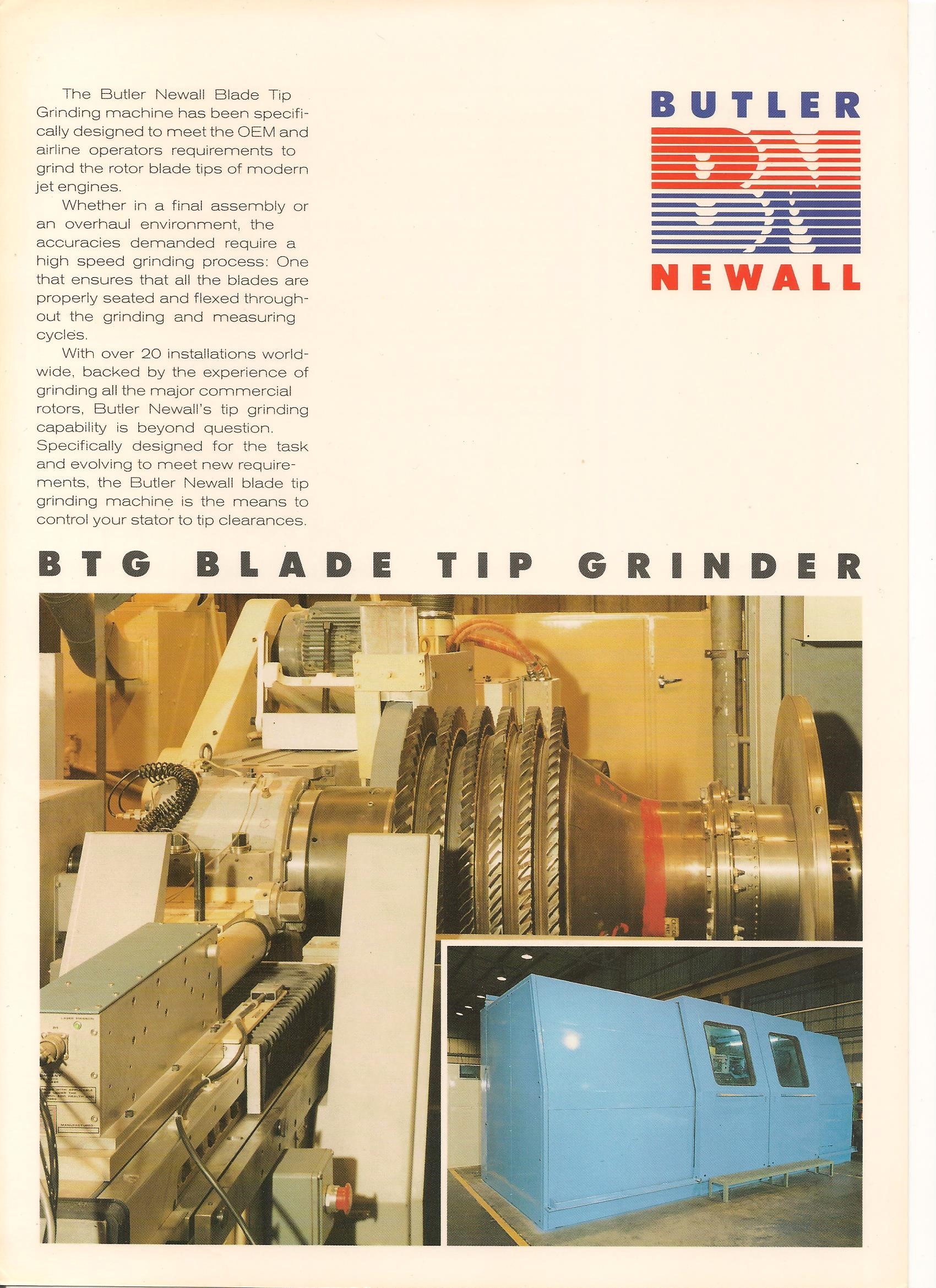
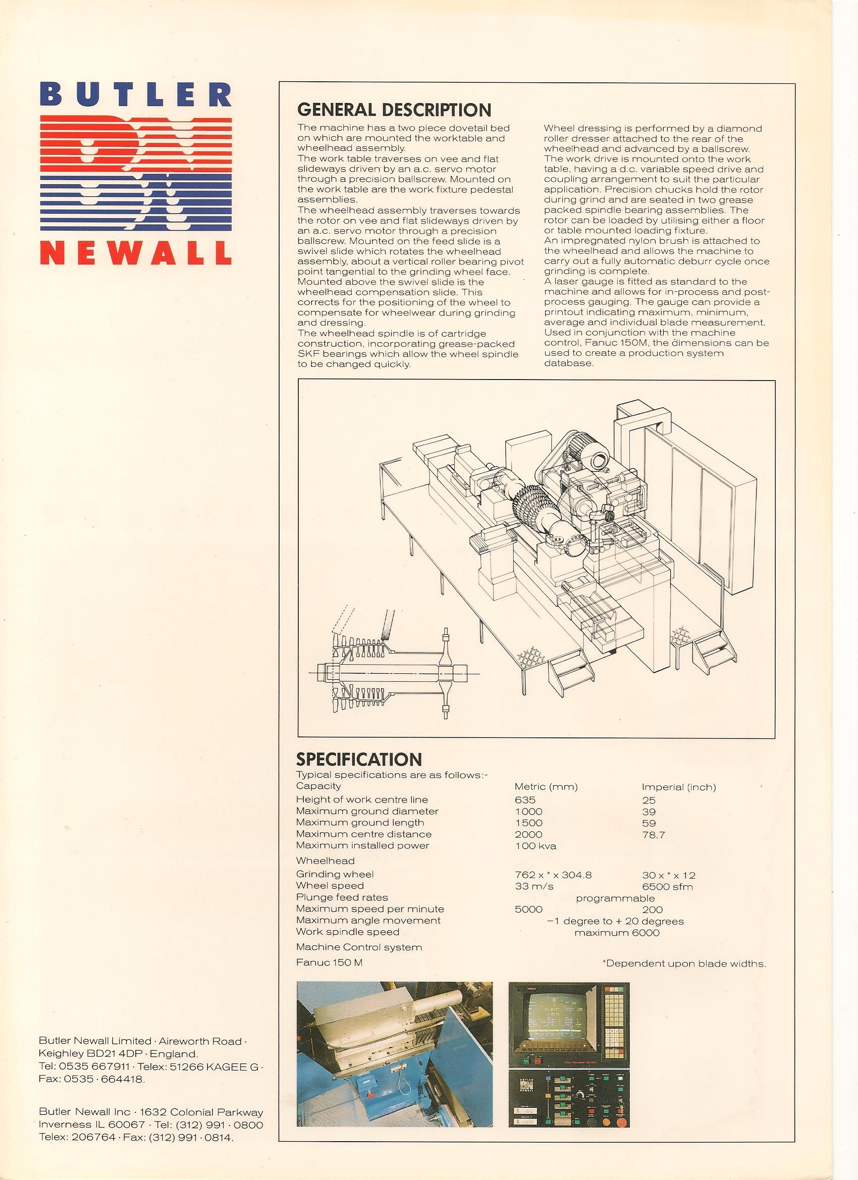
The Blade Tip grinder is featured in a sales brochure produced for Butler Newall entitled ‘High Technology Grinders‘.
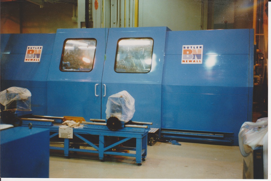
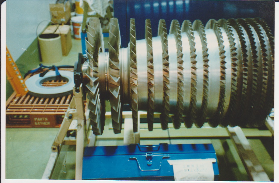
In December 2019 we were pleased to receive the following photos from James Rye of a Blade Tip grinder shortly after installation at ANA (All Nippon Airways) in Japan. They were taken in October 1991.
GAP BED GRINDER
“The manufacture or overhaul of aircraft landing gear is a time consuming and expensive process. A conventional leg is comprised of an inner and an outer cylinder, both components will have been originally manufactured from a solid forging. They are large, unwieldy and, not least, very expensive components.
“The Challenge. Find a means by which both the inner and outer cylinders of a landing leg can be ground on one machine with minimum set up time. On each of the components a variety of tasks may have to be performed, from deep internal bores on the outer cylinder to small internal diameters of the ‘trunnions’ of the inner cylinder, as well as conventional grind of external surfaces.
“The Solution. Produce a machine with an expandable gap between the workhead and table. By so doing, the classic ‘T’ shaft of the outer cylinder can be swung in the gap. Offer a range of external wheelheads from a plain external with the option of a ‘pull down’ internal wheel spindle to cope with those awkward bores, through to a full universal wheelhead with a deeper bore internal attachment mounted on the rear. Further flexibility can be achieved by the addition of a second carriage to accommodate a dedicated deep bore internal spindle. Control of the range is accomplished by a state of the art CNC system incorporating a wide variety of operator and process information.”