Page added in October 2022.
VERTICAL MEASURING MACHINE
In October 2022, we discovered a feature from an engineering journal (“The Engineer”) published in 1965, describing a vertical measuring machine based on a 2443 jig borer. The description below is how the Newall machine was described in their advertorial.
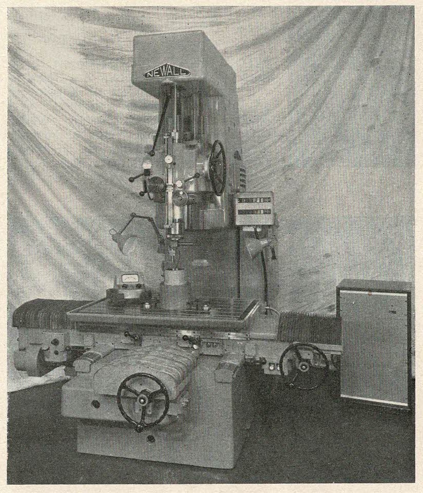
The Newall measuring machine we illustrate provides facilities for linear measurement in right-angle planes. It is equipped with diffraction gratings, made by Optical Measuring Tools Ltd., which are mounted in the bed and used in conjunction with reading heads mounted on the table slides. The moiré fringe patterns which are produced by the interaction of the fixed scales and index gratings in the reading heads are counted electronically and displayed on a two-axis read-out panel at the side of the machine column.
The system provides for a digital display of the actual co-ordinate displacement of the worktable from the zero position and also incorporates full zero shift facilities. Digital readings are in increments of 0.0001″ and settings to less than 0.00005″ are obtainable by reference to a fiducial indicator. The system is arranged to give an additive count in either direction from the zero position on the X- and Y-axes, the direction of count and table travel being shown by an illuminated arrow. This measuring system has particular advantages with its in-line digital display of the worktable position, the automatic reversal of direction of positive dimensions and the fact that the digital display portrays a direct reading of worktable displacement from a selected zero.
Although the table-measuring range is 24″ by 18″ the open-side construction of the machine permits workpieces of much larger area to be accommodated. The actual working surface of the table is 24″ by 43″ and for coarse setting purposes it can be traversed at up to 90″/min. It is claimed that the parallelism of the table surface in longitudinal and transverse movements is within 0.0002″ and the maximum departure of the table surface from the mean true plane is +/-0.00015″. The squareness between table longitudinal and transverse movements is given as 0.00015″ over 18″.
The spindle is mounted in ultra-precision, pre-loaded bearings and it is rotated by a small handwheel through gearing and a belt arranged to prevent side-loading. When rotated the spindle is capable of tracking a circular path to within 0.00002″. The spindle head can be adjusted over a maximum distance of 14″ on the column, and with the 9″ movement provided in the spindle quill, distances from 9″ to 32″ are available between the spindle nose and the table surface.