This web page was last updated in October 2019.
[[The little feature on the Newall-Agietron Spark Erosion machine on our Newall Engineering Products Page 3 was compiled from information supplied by John Seiffert, formerly of Matchless Machines Ltd. A number of subsequent emails between John and the writer (mainly questions to him about EDM in general and the spark erosion process in particular) resulted in a lot of information coming our way. As we have had little direct experience of this method of machining, we found this information interesting and illuminating. It was considered a little “heavy” to reproduce in the main body of the website, but it seemed a shame not to record it, so we have tucked it away on this page for those who might be interested. John Seiffert is now 85 years old (in 2019) and has lived in New Zealand for much of his life. We asked John numerous questions, to which he has responded in this compilation.]]
The process is the original from which the wire erosion was developed. An electric discharge jumps from one electrode to the other across a small gap, anything from a few microns to tenths of a millimetre. The gap is filled with a so-called dielectric, usually one of the paraffin families. (Wire erosion uses water!) Typically, the upper electrode, the tool, is positive, the lower one (the workpiece) is negative. (When machining tungsten carbide they are reversed.) Each discharge removes a microscopic amount of the workpiece, is quenched by the dielectric and washed away into the so-called “pump and filtration unit”. The macro effect is that material is removed from the workpiece. The upper electrode is often either copper or graphite and has the exact shape but in mirror image of the final shape required in the workpiece.
We commonly speak of the tool as the “electrode”. Generally, the electrode is held in the quill, uppermost on the machine; the workpiece clamped on to the worktable. There are no cutting forces involved, but there are hydraulic ones as a result of the flushing of the swarf out of the gap, rather like a pumping action, hence the need to clamp the workpiece. The swarf is actually spherical, often collecting into small bundles, before they are washed away.
There are basically three or four parts of any spark erosion machine:
- The base with worktable and upper quill.
- The generator to produce the sparks.
- The dielectric pump and filtration unit.
- The high-pressure hydraulic pump for the quill feed mechanism N.B originally, the feed mechanisms were purely mechanical (i.e. no hydraulic pump). Later, hydraulic systems were introduced. Nowadays they tend to be purely electrical.
The quill feed is servo driven. The gap in the dielectric between the tool and the workpiece is measured and held at the optimum level for erosion to take place. As erosion takes place the gap opens, and the servo tells the quill to advance towards the workpiece. Conversely if it gets too small, and there is a danger of a short-circuit, the servo will open the gap. We are talking increments of microns at a time here. The original servos were stepping motors, and a wonderful system of differential gearboxes. Later, the hydraulic servo used a “Pegasus” valve like the Moog. (The earliest machines circa 1954 used an air valve!) At the end of the process, by which time the whole form has been produced in the workpiece, an end switch interrupts further processing and the quill returns to its home position.
For the Newall/AGIE joint venture, Newall made the cross-slide, the base and table. AGIE made the head containing the quill and servo, the generator, and they also procured the high-pressure oil pump from SIG. Matchless made the pump and filtration unit and assembled the whole thing.
Materials used: Copper, graphite or even aluminium as well as steel as the electrode; the workpiece was any electro-conductive or even semi-electro-conductive material. Die steels were the most common in toolmaking, i.e. forging dies, plastic moulds, pressure die-casting tools, extrusion dies, press-tools etc., also all sorts of exotic materials dreamt up by the likes of Rolls Royce for their gas turbines. The process grew up with toolmaking in mind, but in later years progressed into components, most notably in the aerospace industry.
The current put out by the generators ranged in my day from about 5 amps to 1000 amps at a typical gap voltage of 40-60 volts. Nowadays the current is much lower, thanks to much more sophisticated electronics. The Newall-Agie had the option of either 45 or 75 amps. Stock removal rates were from almost nothing for finishing to rates near to milling for large machines. Strangely the rates of stock removal “Vm” were quoted in imperial. The Newall-Agie was 2.9 cu inches/hour (0.049 cubic inches / min) whereas my own 1000-amp machine did about 38 cu inch/hour!
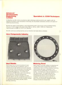
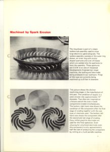
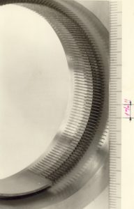
The advantage of EDM was clearly the ability to work very hard (and indeed fully hardened materials), obviating problems of heat distortion after milling and grinding. There was no machining force, which made all kinds of applications in the aero industry possible, notably the machining of honeycombs for gas turbine seals, heat shields and turbine blades.
The process was unattended in the main. Not everybody had a good means to machine the electrodes. Copy-milling and engraving machines helped, as did the likes of Thiel punch-shapers for those making press-tools. Cold forming of copper was often used in the coin, toy and jewellery business. The roughing electrode was usually undersize by about 0.1mm or less, with the finishing electrode typically 0.002 – 0.005mm. Not everyone could achieve this. Machining times were hard to predict. However, on one occasion here in NZ a customer took at least a week to mill a large mould, I did it on an elderly Agie in one afternoon. Another “pro” was the fact that on a good EDM machine there was little if any hand finishing to do on a mould. That cannot be said today with high-speed milling.
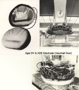
Agie were the ONLY firm to enable steel into steel to be used. This was an absolute godsend for the large die makers, particularly car body die makers, as they could spark one half of the die against the other, doing away with what was known in the car trade as “barbering” The process resulted in there being no flash between the die-halves.
[[We asked John if the process always uses a full-form electrode with simple linear downwards movement of the Z-axis, or could it emulate a CNC contour milling operation by using a single point tool moving in 2 or 3 axes.]]
On the question of axis, Z etc., let me please explain. Most of my above comments apply to earlier machines, and even simple ones today. However, the advent of advanced electronics and CNC gave change to all that. In the mid to late 70s CNC took over. Agie had already pioneered the additional axis other than “Z”; in fact, I supplied a number of machines with additional servo on either X or Y or both. CNC made it possible to have servo on all three axes simultaneously. System 3-R brought out a head that up-graded old machines to give that same “orbital” movement. Good machines like Agie, Charmilles etc. have it now as standard.
[[John went on to reminisce about his time working in the UK and New Zealand.]]
I could go on ad nauseam on many aspects of this. I not only sold 800+ standard Agie machines in UK, another 50 in NZ, but we also serviced them in UK, and there I had a rebuild section with 36 people re-building Agie and Studer (grinders). We re-built around 60 machines of each make, even for Swiss companies (inter alia the Swiss Airforce)! In addition I owned and operated two subcontract EDM machine shops, one in Horsham with about 13 machines, including the famous Newall-Agie as well as a SIP-IH EDM for relatively small work, and another in Bletchley a fully owned subsidiary ADE with a further 16 machines for bigger work and particularly for Rolls Royce, who represented about 80% of the work. In Bletchley I had a 1000-amp machine. From a sales point of view, we were able to “buy back “old machines so that customers could buy new, because the old ones were then put into Bletchley, where no-one knew better than us how to use them!
You may be interested to know how the sub-contract started. Agie had produced the world’s first wire-cut spark-eroder (WEDM). The founder of Agie was my late son’s Godfather and he showed me the prototype one evening after dinner at his home in Locarno. When it was available, I took delivery of a few of the machines. They cost around £11,000. No one bought or even believed in them. But I knew they would (and did) revolutionise toolmaking, and one day my accountant (who later bought me out and promptly closed the business which went into receivership – nearly 200 out of a job!) came to me complaining about the amount tied up in stock we were not selling. I told him to go and rent a building where I put the stock machines to work. Soon the industry begrudged me the profit I was making and in one year I sold 50 such machines. RR wanted capacity when the RB 211 went into production. We made 64,000 heat shields for them alone on 4 old machines we had “bought back” as well as countless other things. We even supplied Bofors in Sweden with dies for their massive crank-shaft dies.
[[John also sent us the following documents and photos.]]
[[We asked John if the latest developments had replaced EDM as a machining process. He responded that:]]
High speed milling ( spindle from about 40,000 up to and more than 100,000 rpm) mean that the machines are ultra expensive. Mikron make the best ones, also owned by +GF+. They are also very sensitive to shock, a simple tap by a collet spanner can destroy one of those spindles and they take a long time to warm up anyway. Ceramic, and now water bearings have changed that a bit, but nevertheless daunting. The result is that smaller, less “well-heeled” toolrooms still prefer EDM. Agie have a well developed extra high precision range for micro-technology, and the WEDM ( wire) machines are still made in large quantities.

